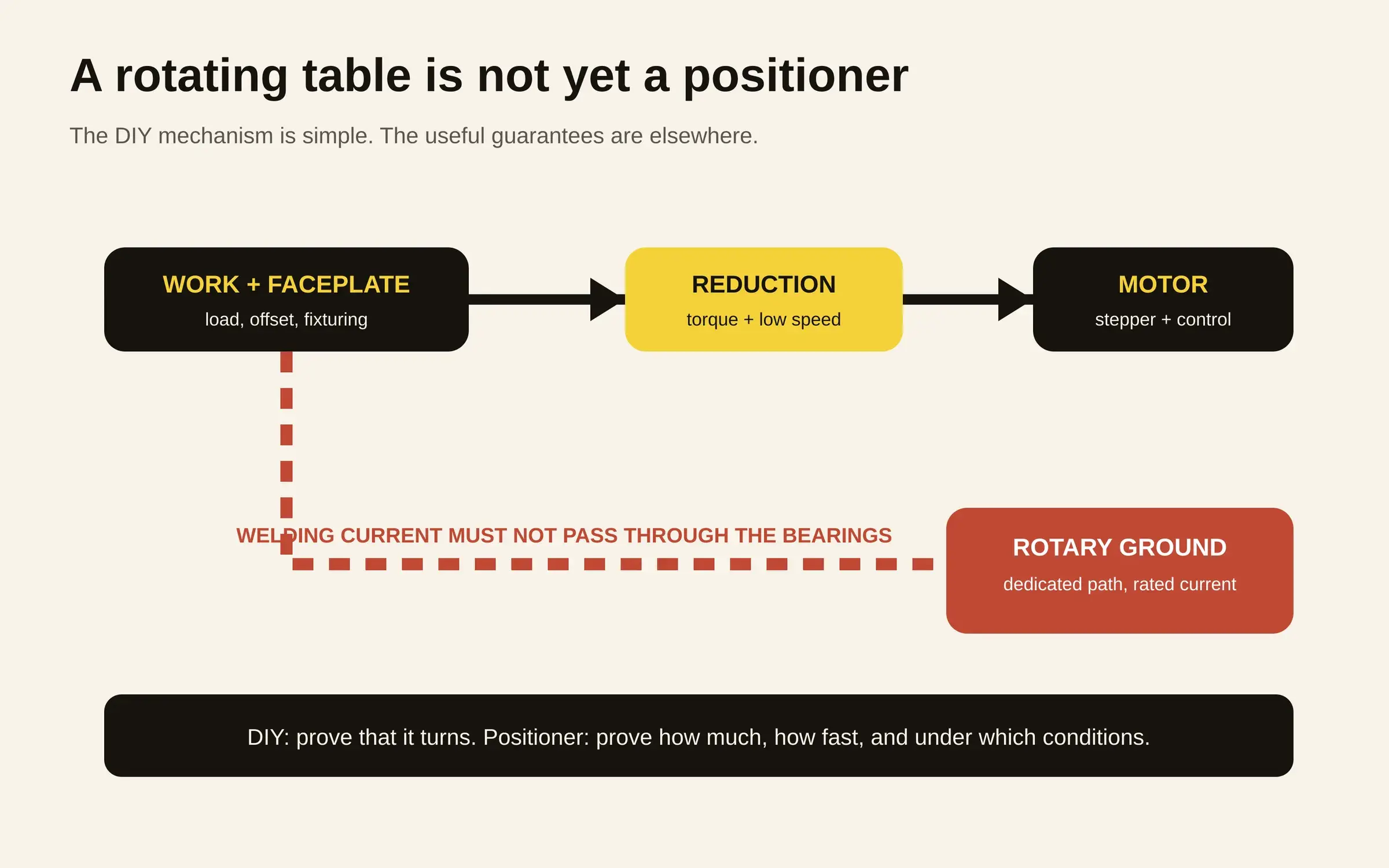
Greenhill Forge’s project first looks like a large motorised Lazy Susan: a fabricated table, a large circular bearing, a stepper underneath and enough electronics to choose the rotation speed.12
That apparent simplicity is precisely why the build is useful. A welding positioner seems like an uncomplicated machine until somebody asks how much it can carry, how far that mass may sit from the axis, how slowly it can turn, how much torque remains there, and where several hundred amps of welding current are supposed to go.
Greenhill demonstrates the motion, while commercial manufacturers mostly sell documented answers to the questions that come afterwards: load, torque, current capacity and the conditions under which those numbers remain valid.
It turns
The public bill of materials can be reduced to a few understandable blocks. Hackster describes a large Lazy Susan bearing, stepper motor, gear reducer, standard spider coupler, Arduino UNO Rev3, rotary encoder and small OLED display.2
The operator sets a speed, the Arduino drives the stepper, and the reduction stage turns that motor motion into a slow faceplate rotation. For a circular seam, the welder can keep body and torch much steadier while the joint moves past them.
Nothing about the principle is exotic, which is part of its appeal: almost every function is visible, replaceable and understandable in an ordinary fabrication shop.
Neither the video nor the discovery article publishes a rated payload, faceplate torque, eccentric-load limit or measured RPM range, however.12 Assigning a capacity from the apparent size of the motor or the stiffness of the frame would therefore be guesswork.
Right speed
For a circular seam, what ultimately matters is the linear travel speed at the weld while the machine itself is adjusted in revolutions per minute.
Geometry connects the two:
rpm = linear speed / (π × diameter)
Use a purely illustrative target of 300 mm/min, rather than pretending there is one universal welding speed. A 100 mm diameter joint needs about 0.95 rpm; at 200 mm the same surface speed requires 0.48 rpm, and at 300 mm only 0.32 rpm.
Commercial specifications make sense in that light: Miller lists 0.5–7.5 rpm, 0.3–10 rpm or 0.1–3.2 rpm depending on ZB-75 variant,3 while the ZB-300 family goes as low as 0.07 rpm on one model and as high as 24 rpm on another.4
Maximum speed is easy to advertise, but with larger work the more revealing ability is turning slowly and smoothly while useful torque is still available, because the required rpm falls as diameter rises.
The load
A balanced horizontal table is the easy case; once the faceplate is tilted vertically and the centre of gravity moves away from it, the drive is no longer overcoming mostly friction because gravity creates a moment around the axis.
Manufacturers therefore do not simply print “136 kg capacity” and stop. Miller rates the ZB-300 for 136 kg vertically with the centre of gravity four inches from the faceplate, and 204 kg horizontally at the same distance.4
The smaller ZB-75 is rated at 34 kg with the faceplate vertical and 45 kg horizontal.3 Bancroft’s TT100 carries 45 kg and publishes 350 in·lbs of torque at 7 rpm, roughly 39.5 N·m.5
Greenhill does not publish that operating envelope yet. This says nothing sinister about the build; it means the prototype has not been characterised as a rated positioning machine.
The current
Perhaps the cleverest part of the build is the one least visible in a photograph: the welding-current return path.
Clamp the welder return to the stationary frame while the work rotates through a bearing and current may find a path through balls and races. Tiny arcs across those contacts are an excellent way to turn a bearing into a consumable. Clamp directly to the rotating faceplate instead and the lead eventually winds itself around the machine.
Greenhill runs a copper ground strap against the motor shaft, creating a sliding electrical contact to the table.2 Hackster notes that the copper becomes a wear item, which is a much better sacrificial component than the bearing itself.2
Commercial machines turn the same idea into a rating: Miller gives the ZB-75 a 300 A rotary ground,3 and Bancroft specifies the same 300 A figure for the TT100 welding ground circuit.5
There is a meaningful distinction between “the strap conducts” and “the return assembly is rated for 300 A”. The second statement begins to define an operating envelope.
High frequency
Electronics introduce another complication, particularly around TIG high-frequency starting.
Miller explicitly lists high-frequency protection for the ZB-75.3 That is not merely catalogue decoration: another Arduino-controlled positioner project, published by CodeMakesItGo, reports running into electromagnetic interference caused by a TIG welder’s high-frequency start.7
An Arduino, display, encoder and stepper driver therefore live in a rather harsher electrical environment than the same parts on a desktop project. Enclosure design, grounding, cable routing, filtering and isolation become part of the positioner even though none of them moves the faceplate by a degree.
Real cost
Calling the Greenhill build “affordable”, as Hackster does, is reasonable in the sense that it uses common components and a shop-fabricated structure.2 What the public material does not provide is a priced BOM from which an exact total can be verified.
Commercial prices can at least establish the other side of the comparison. Bancroft currently lists its TT100 at a $1,580 base price: 45 kg capacity, 12-inch aluminium table, 0–90° tilt, digital RPM display, 0–15.75 rpm speed range, 350 in·lbs at 7 rpm and a 300 A ground circuit.5
Lima Equipment lists a 100 lb horizontal welding positioner at $999, with tilting products higher in the range.6 Those figures do not justify claiming the DIY is “X times cheaper” when its exact cost is unknown. They show what several hundred or several thousand dollars can buy beyond the motor: a published operating envelope.
Add measurements
Turning the Greenhill build into a tool whose limits another shop could understand before loading a part would not necessarily require much more hardware. It would mostly require measurement and publication.
A first data sheet could record minimum and maximum speed under load, faceplate torque or at least tested mass together with its centre-of-gravity offset, current capacity of the sliding return, motor and driver temperature, then the conditions used for MIG and TIG tests.
An accessible stop control or foot pedal also deserves consideration. The ZB-75 supports foot control for a practical reason: while the bead is running, both hands can stay where they are useful.3 Hackster’s description of the Greenhill build mentions the rotary encoder and OLED but not a foot control.2
The copper return strap should also be treated as an inspectable consumable because its wear is precisely what keeps the rest of the mechanical current path out of the job.
Nearly there
Greenhill’s project is not interesting despite these blank specification boxes. The blank boxes are what make the project revealing: they show how accessible the mechanism of a useful positioner can be to a properly equipped workshop.
A bearing, reduction drive, motor and controller produce the movement. Then arrive centre of gravity, torque, very low speed, hundreds of welding amps, TIG high frequency, foot control and repeatability.
That is the point where a rotating Arduino project stops being merely a successful machine that turns and starts becoming a welding tool another person can trust within known limits.