

A modern airliner carries a dozen radio systems: VHF, satcom, GPS, transponder, radio altimeter, Wi-Fi, data links. Each has its antenna, and all of them share the same forty-meter metal tube. The question that decides whether this crowded neighborhood can transmit at the same time comes down to one number: the energy that leaks from one antenna into another, sometimes ten billion times weaker than the transmitted signal.
That number is called isolation between antennas, it is measured in negative decibels, and the white paper WIPL-D published with IEEE Spectrum in August 202612 tackles a specific case: predicting it by simulation when the coupling drops to -100 dB, on a platform that does not exist yet. Not after the prototype. Before the first rivet.
This is a software vendor's document, and it should be read as one. But the problem it describes is real, documented for decades by navies and air forces, and the way it gets solved says something that goes beyond EMC: in some trades, the physical prototype has been replaced by a computation whose hardest part is the model's tendency to lie, more than its size.
The hidden coupling
The trade's term is co-site: several transmitters and receivers forced to share the same physical location. On a warship, antennas pile up on a single mast because no naval architect will hand over twenty extra meters of real estate for spectral comfort. On an aircraft, they share the fuselage. On a ground vehicle, the roof.
When a transmitter runs, it does not only send its signal skyward. A fraction of its energy lands on the structure, wraps around obstacles, reflects, and eventually arrives at the port of a neighboring antenna. That leak is described by the mutual S-parameters between the two antenna ports, and it decides whether two systems can operate simultaneously on the same platform1.
Why worry about such a ridiculous leak? Because a receiver is built to catch minuscule signals. A sensitive receiver works down to the nanowatt and below. The leak arriving through the neighboring mast does not need to be strong: it only has to land in the useful band, or create intermodulation products, to jam the reception.
The mechanisms at play fall into two families that co-site practitioners sort methodically5. In-band: spurious emissions from the transmitter landing directly in the neighbor's passband, intermodulation products when several transmitters speak at once and cross nonlinear components, broadband noise. Out-of-band: signals exciting the receiver's spurious responses, typically in its mixers. The symptom list reads like daily life: crackle in a headset, a GPS receiver losing satellites, a link's range collapsing because the receiver goes deaf5.
The military industry has a name for it, picked up in a long Military Aerospace Electronics feature: "spectral friendly fire"5.
That 2017 article quotes John Franklin, an engineer at CERDEC, the US Army's communications R&D center: "There are some systems that cannot be run at the same time on the same platform." He adds that an aircraft usually stays out of the air while co-site problems remain; the Army, for its part, fields ground platforms anyway5.
A destroyer gone quiet
Coupling's consequences don't stop at spec sheets. The textbook case is dated and documented: on May 4, 1982, the British destroyer HMS Sheffield was hit by an Argentine Exocet off the Falklands. Twenty dead; the ship sank on May 10.
The Royal Navy's board of inquiry and the reconstructions published since describe a stack of failures, and coupling was not the single cause. Let's be clear about that: the sinking had several fathers. But one link in the chain sits exactly on the problem at hand. Sheffield was assigned the satellite link back to London; the satellite uplinks of that era operated in the radar band, and the ship's air search radars could interfere with that link. According to historian Norman Friedman, the ship switched off its radar warning receiver and its air search radars during satellite transmissions7. The board of inquiry separately noted that the UAA1 sensor was blocked at the critical moment by an unauthorized transmission from the ship's SCOT satellite communications system6.
In other words: two radio systems on the same ship could not coexist cleanly, and the workaround was to silence one whenever the other spoke. Antenna coupling, here, does not cost decibels. It costs a window of detection.
Satcom raised the other end of the problem: what the ship transmitted without meaning to, more than what it received. During the war, an Argentine university discovered that a ship using its satellite link could be tracked passively, just by listening to the downlink, and an Argentine Boeing 707 converted into a survey aircraft confirmed the method against the task force itself7. An antenna leaks in both senses of the word: the spill that bothers the neighbor is also a signal that gives you away.
That kind of story explains why navies have funded co-site prediction and mitigation programs for years, and why the framing of "high-power emitters next to sensitive receivers on a platform you cannot enlarge" repeats almost verbatim across the field, from the Navy to Lockheed Martin5.
Trial and error, grounded
The tinkerer's instinct would be: measure it. Build the mock-up, walk the antenna around, write the numbers down. That is exactly how it used to be done, and it is precisely what no longer scales.


First problem: the platform is electrically large. At 1.06 GHz the wavelength is about 28 centimeters; a 40-meter fuselage therefore spans roughly 140 wavelengths, which matches the white paper's airliner example1. The white paper speaks of platforms spanning "several hundreds of wavelengths" in the general case1. At that scale, every structural detail reflects and diffracts: the leak between two antennas depends on the whole body, not on the two antennas taken in isolation.
More counterintuitive still: the platform changes how the antennas themselves behave. An antenna gets characterized in the lab, alone, in free space. Mounted on an aircraft, its pattern gets distorted by multipath, by diffraction off wing edges, by those creeping waves that follow the curved skin before radiating away. The field's engineers open their slide decks with exactly this: the installed antenna is no longer quite the catalog antenna13. Predicting coupling therefore means simulating the entire platform, not just both ends of the link.
Second problem: measurement happens on a finished object. Nobody cuts up an A320 to move an antenna half a meter, and nobody repaints a destroyer to test a spot. Every candidate position translates into months of engineering, certification, flight or sea trials. The white paper sums it up: measuring by trial and error at every candidate position is slow and costly1.
That leaves simulation. And there, a mathematical obstacle is waiting from the very first line.
Counting the unknowns
The reference method for this kind of problem is the method of moments (MoM) applied to surface integral equations: instead of meshing all the air around the aircraft, you compute the currents induced on the metal surface itself, then derive the fields everywhere else. It is the family NEC, the field's historic code, belongs to.
The history is worth a detour, because it shows antenna coupling has been a simulation problem since the dawn of consumer computing. NEC descends from a program called BRACT, written in the early 1970s by MBAssociates for the US Air Force's Space and Missile Systems Center, on a CDC 6600, one of the first supercomputers9. The lineage became NEC at Lawrence Livermore, where Gerald Burke and Andrew Poggio developed NEC-2 under contract to the Naval Ocean Systems Center and the Air Force Weapons Laboratory, a tri-service-funded program89. The 1981 manual already lists, among the output options, the computation of maximum coupling between antennas9. NEC-2 is also the last fully public version of the code: later ones moved behind license agreements, but thousands of NEC-2 copies were already circulating then, and still circulate now810.
The trouble with naive MoM is the count. A direct solver must invert a matrix whose size grows with the square of the number of unknowns, and the inversion itself costs a cubic order of magnitude. The white paper puts it bluntly: the cubic cost of a direct solve makes every avoided unknown pay back many times over1. Double the frequency, double the mesh density per axis, and compute time explodes.
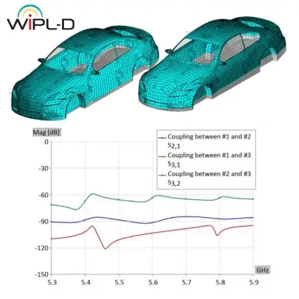
Hence the central trick of modern solvers like WIPL-D: higher-order basis functions, which allow mesh patches up to 2 wavelengths where classic triangular meshing demands a fraction of a wavelength per element. Fewer unknowns for the same geometry1. The vendor's public application notes give the real order of magnitude: a complete F-35, 15.7 m long, spans 78.5 wavelengths at 1.5 GHz and requires about 92,000 unknowns without reduction, simulated on a desktop PC in under an hour3. Two cars talking to each other, six antennas in total: 364,262 unknowns without symmetry, solved in under 30 minutes by their domain decomposition solver, versus several hours in direct MoM3.
The ghost cavity
Here is the most interesting part of the white paper, the part that never makes the brochures: once the model's size is settled, you still have to keep the computation honest.
Any closed metal platform, a fuselage or a hull, behaves like a resonant cavity inside the numerical model1. The physics has a one-image explanation: a closed box lined with metal is precisely the definition of a microwave cavity, the very object labs use to trap waves at known resonant frequencies. The physical object is open: air flows, waves escape. But the model only computes the surface; the inside of the volume forms a closed box in which the solver can trap spurious fields. Those fields do not exist in reality. They are a discretization artifact. And because they add to the true signal at the ports, they saturate exactly the levels we care about, our -100 dB territory.
The white paper is explicit: it is the spurious fields trapped inside, not the platform itself, that spoil low-level results1. The leak you measure in your simulation can therefore be pure computational noise.
The countermeasure takes three moves. First, treat the reference frequency as a convergence test: rerun the computation at a slightly shifted frequency and watch whether the coupling result moves; if it still moves, it is not trustworthy1. Then, suppress the spurious fields with absorbing materials placed inside the model, or with air-filled "bubbles" inserted into the closed structure, two of the three techniques compared in the document1. The white paper publishes the complete geometry of its two case studies, a metal cube carrying two quarter-wave monopoles and the five-monopole airliner, precisely so every result can be checked independently1.
That point contradicts the simulator-as-oracle picture. The hard part of -100 dB coupling is not writing the equation: Maxwell settled that long ago. The hard part is knowing whether the number coming out of the machine is physics or a numerical scar.
92,000 unknowns
Concretely, what does a solved problem look like? WIPL-D, a company founded in 2002 in Belgrade2, ships a dedicated cosite analysis feature in its 2025 CAD environment4, and its public application notes, read with the usual distance owed to a vendor showing off its best cases, give a sense of the orders of magnitude3.
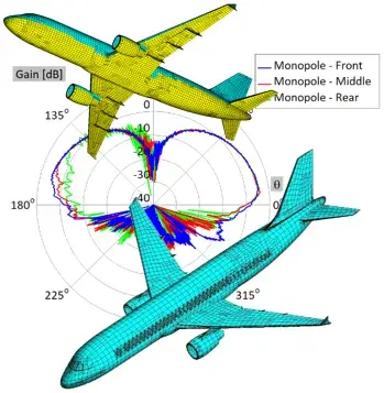
An A320 gets simulated with one monopole at 833 MHz, then with three monopoles at 1.53 GHz at different fuselage positions3. An IFF dipole on an F-16 puts the platform at about 105 wavelengths at 1.9 GHz, with a coaxial feeder 3.16 mm across, 45 times smaller than the wavelength, a detail the mesh has to swallow anyway3. And to stay civilian, two cars talking at 5.9 GHz with six antennas demand the quarter-million unknowns already quoted3. The same tool family hunts subtler effects: three patch antennas on top of a helicopter at 2.625 GHz, simulated with the rotor in three different positions, show that rotor rotation mostly scrambles the front antenna's pattern and barely touches the rear one3. Here the platform physically moves while its antennas transmit.
The coupling between the two cars' antennas, as the vendor's figure traces it, drops between -60 and -120 dB depending on the pair and the frequency3. In other words, the working range of co-site engineers sits far below what a benchtop analyzer measures without precautions.
What the model cannot see
Simulation predicts electromagnetic coupling between geometries. It does not predict everything, and the white paper itself bounds its scope: it predicts isolation, it says nothing about the electronics behind the ports1.
Real co-site mixes both worlds. The Military Aerospace Electronics feature details what a bare S-parameter misses: harmonics and spurious emissions from transmitters, intermodulation products when several transmitters speak at once, broadband noise, out-of-band receiver responses5. Computed coupling is one brick; a complete co-site analysis stacks that brick with the radios' actual specs, filters, cables and operational constraints, which channels will really be used, which systems will never power up together5. That is also why the mitigation catalog goes far beyond moving antennas: changing channels, adding filters, adjusting clock types, swapping radios, applying material treatments that reduce coupling5. Each option carries a cost, a weight and a delay; the computation exists precisely to choose before paying.
There is also the gap between the model and the machine. A fuselage gets modeled as a smooth metal surface; the real one carries rivets, joints, paints, internal wiring the model ignores. Practitioners put it differently: simulation guides and reduces testing, it does not eliminate it. The 2017 article paraphrases Lockheed Martin on the state of the art: modeling and simulation during the design phase, anchored in known operational or test data, so that by fielding time you know what will need fixing5. And when simulation is not enough, bureaucracy takes over: Franklin describes a stove-piped acquisition process where one program manager buys radio A, another buys radio B, and nobody claims ownership of the fix when the two interfere5.
And one factor survives both measurement and simulation: the decision. Sheffield probably knew its radars and its satcom were fighting over spectrum; the chosen workaround, silencing one while the other spoke, was an organizational decision, not a computational error. The best model in the world does not replace the question "what do we do when two systems cannot coexist?"
The inverted prototype
What interests me here is not WIPL-D's software. It is the reversal of method the subject illustrates.
Maker culture runs on a short loop: print, measure, correct. That is its strength, and it is what this site usually writes about. But a whole class of problems never enters that loop, because the test object exists as a single copy and the test costs a warship or an airliner. For those problems, the loop moves into computation: the prototype becomes a model, and the craft hides in knowing whether the model lies, the convergence test, the hunt for spurious fields, the comparison across neighboring frequencies.
The good news is that this discipline is not reserved for naval design offices. The 1981 NEC-2 is still public810, it runs on a ten-year-old machine, and its ecosystem is still alive: xnec2c wraps it in an open source GUI with 3D radiation views11, 4nec2 packages it for Windows, and MMANA-GAL offers the same approach through MININEC12. A radio amateur who wants two antennas on the same mast performs exactly the white paper's computation, at a scale where convergence can be checked by hand. The orders of magnitude change; the method does not: count the unknowns, doubt the result, perturb it to see whether it holds.
The WIPL-D white paper sells a solution. Seen from a workshop, it mostly documents a broader shift: forty years after NEC-2, the hardest part of making things is no longer always building the object. It is knowing, before building, whether the number meant to guarantee it is a physical fact or the shadow of an artifact. No rivet will reveal that.