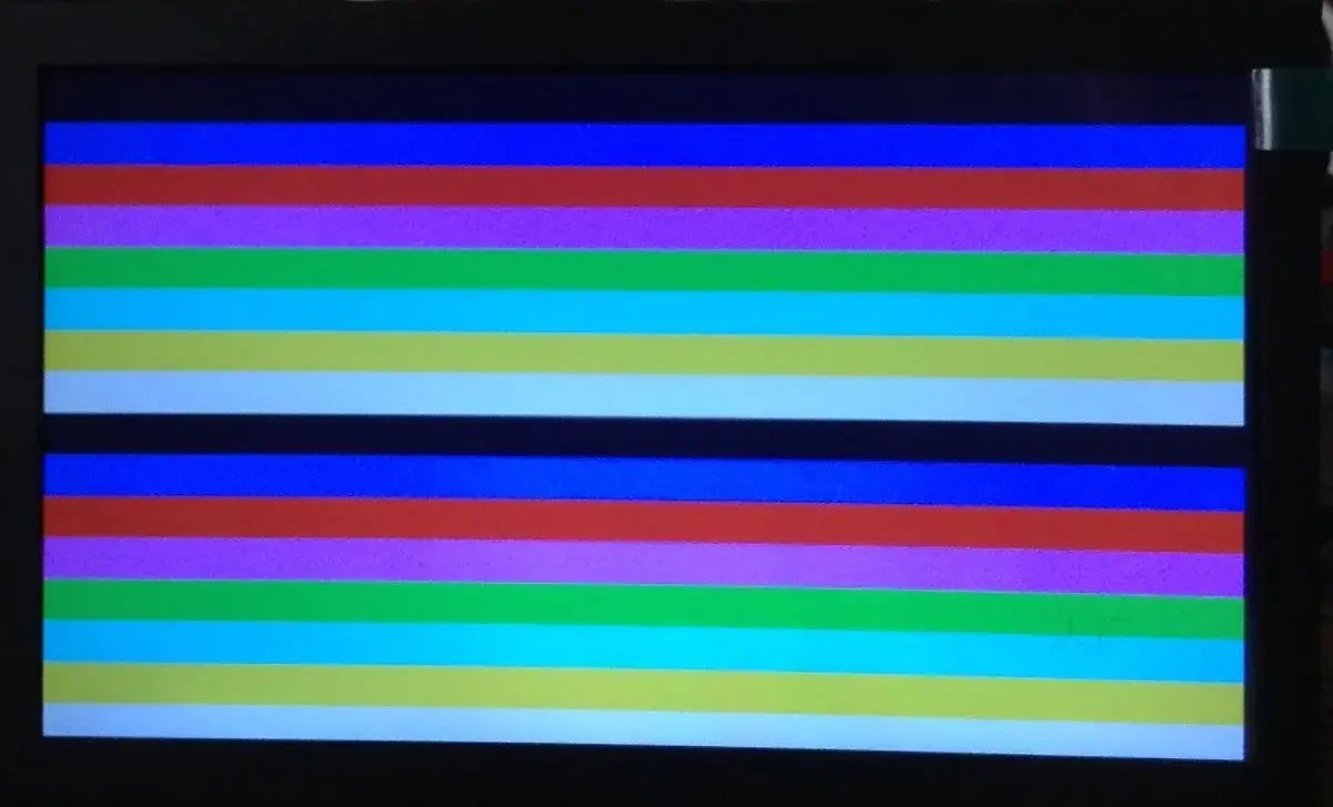
The screen did show the ZX Spectrum colors. None of them looked right, though: everything seemed washed into a dirty gray, including what should have been bright white. Neither the monitor, nor the resistor DAC, nor the video library was at fault. One single black pixel was missing from the end of each line.
That detour through a dull screen is the latest stop in Simplified Pico VGA, a series Kevin has been publishing since July 1. His goal fits in one sentence: do VGA on a Raspberry Pi Pico without treating the scanvideo library like a black box. With a personal constraint that complicates things a bit: staying inside the Arduino environment 2. Adafruit picked up the series in late July, then again on August 24 3.
Seventeen pins
The official starting point spares no expense. The RP2040 hardware design manual documents an example board that produces VGA with three resistor DACs, five bits per red, green and blue channel. Five pins per color, plus HSYNC and VSYNC: seventeen GPIO for video alone 4. A stock Pico exposes twenty-six pins, so that doesn't leave much room for anything else.
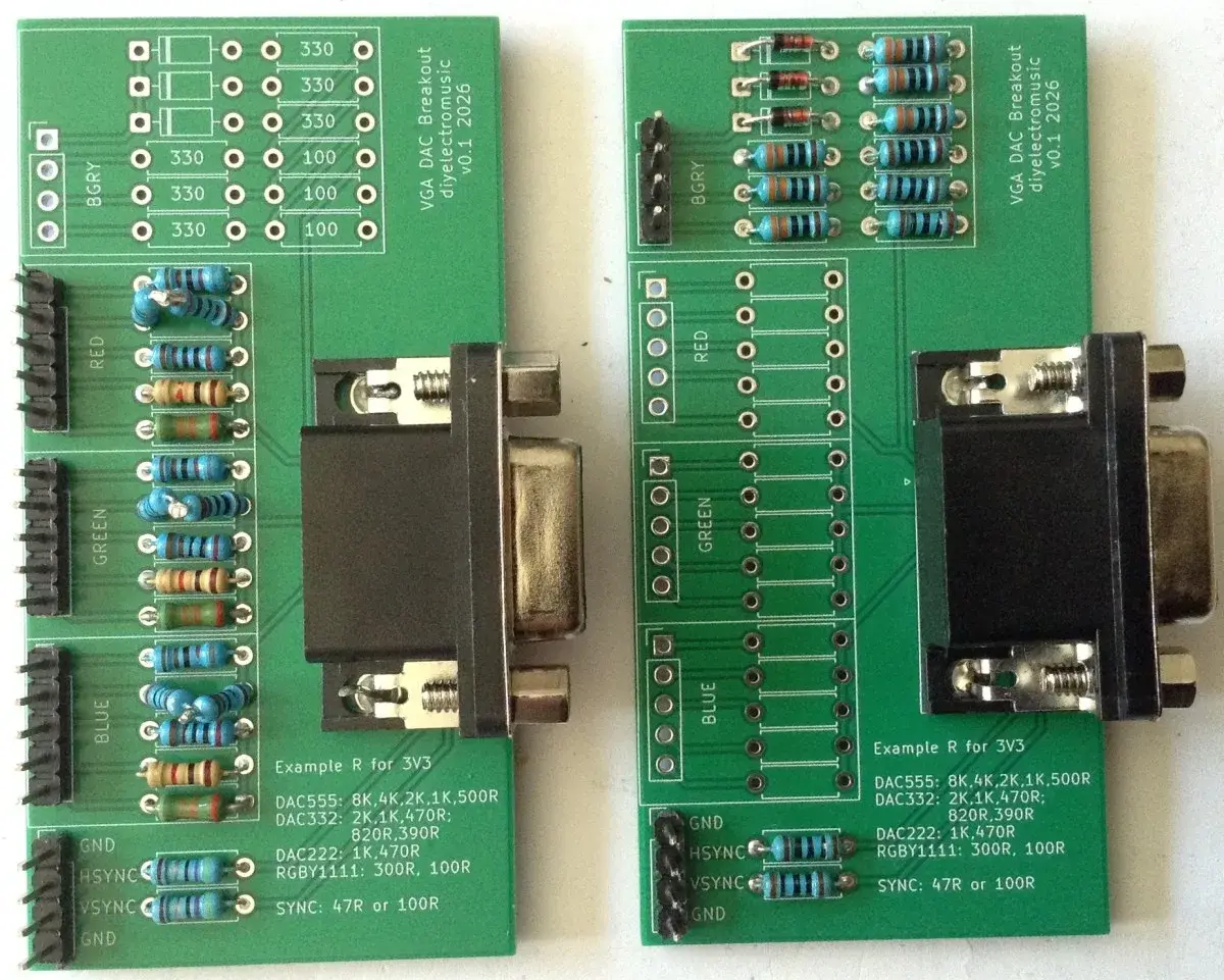
It's the design behind Pimoroni's Pico VGA Demo Base, which wraps it with an SD slot and I2S audio output 5. For breadboard work, each channel wires up as a five-resistor ladder — 8K, 4K, 2K, 1K, 500R — with two 47R resistors on the sync lines 2.
Seventeen pins is the price of convenience. The rest of the series spends its time haggling over it.
Hunting wires
Before writing anything, Kevin surveyed what already existed, and every project tells a different trade-off story.
Miroslav Nemecek's PicoVGA gets down to nine pins by moving to R3G3B2: three bits of red, three of green, two of blue, plus composite sync. Its author owns the math: with 264 KB of RAM, anything beyond 8 bits per pixel makes little sense on RP2040, and dithering claws back part of the loss 6. That project has since been superseded by DispHSTX, which uses the RP2350's HSTX peripheral to drive DVI and VGA alike 7. Another route, another purpose: MCEBlaster reads period-correct TTL signals from MDA, CGA and EGA cards and converts them for a modern VGA monitor, using eight pins — two bits per color plus both syncs 8.
The breakthrough came from somewhere else entirely. While trying to recreate the ZX Spectrum palette, Kevin stumbled onto pico-zxspectrum, which drives VGA in a mode called RGBY1111: blue, green, red on one pin each, and a fourth pin carrying brightness 9. That Y is inherited straight from the 1982 Spectrum architecture: its color attributes apply to eight-by-eight blocks, and brightness hits the whole block. Fifteen genuinely distinct colors — black exists in a "bright" version, hence duplicated — were already enough for the games of the era.
From seventeen down to six. What you pay with is nuance: no soft orange or pale blue here, just fifteen blunt shades.
Pixels as instructions
What remained was understanding how scanvideo actually drives those pins, and that's where the series gets really good.
The library lives in pico-extras 10. The CPU never touches the pins. It fills buffers with sixteen-bit tokens, DMA pushes them toward a PIO state machine, and the PIO streams pixels out at whatever rate the mode demands. For the default mode the docs assume 5-5-5 plus an optional transparency pin, all movable through build definitions 10.
The trick hides inside the PIO program named video_24mhz_composable_default 11. Its first useful instruction is out pc, 16: it takes sixteen bits from the data stream and loads them into... the program counter. Every token chooses what runs next. A COLOR_RUN token jumps to the block that puts a color on the pins, reads a pixel count, loops over it, then fetches the next token. Flat areas become very compact — the docs describe it as run-length encoding for solid color regions 10 — and two timing parameters even get rewritten at runtime to stretch pixels for the target resolution 11.
I've rarely seen a data bus play the role of a program this literally. The image and the instructions that draw it live in the same memory.
The Arduino detour
Officially, you consume scanvideo in C with the Raspberry Pi SDK. Kevin insists on his Arduino IDE, so he moved the library over by hand onto Earle Philhower's Arduino-Pico core 12.
The files go flat into the sketch folder. The two PIO programs must be assembled first: he pushes the .pio files through Wokwi's pioasm tool and pastes the result into two headers. And since video modes are configured through preprocessor definitions compiled deep into the library's C files, a simple #define before the include isn't enough: he grafts a small vgamode.h straight into scanvideo.h. The function that ran on the second core splits between setup() and loop(), the Arduino way of saying "initialization" and "infinite loop".
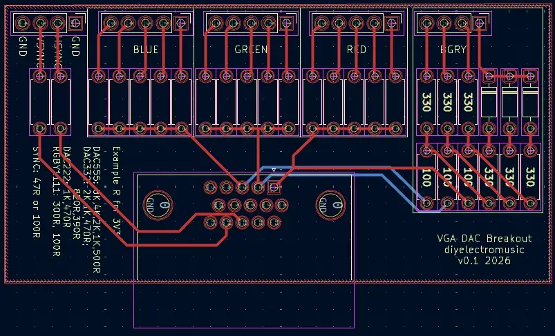
Kevin also designed a test board sitting between the Pico and the VGA socket, published along with its schematic 13. One honest detail from his post: the printed text recommends 300R + 100R for RGBY1111, but the correct value is 330R, as silkscreened right next to the parts.
Everything went gray
First attempt at RGBY1111: the right colors show up, but all too dark. The bright white bar at the bottom of the test pattern comes out a dingy gray.
The investigation runs three acts. First, Kevin suspects buffer structure: his line was one big run where the official example chopped every line into thirty-two chunks. He mimics the chunking and the image looks correct. Then the oscilloscope shows something sharper: on the failing version the blue pin stays constantly high, while the working version drops back to zero, synchronized with each line 2.
The real culprit isn't the chunking. It's the black pixel that comes with it: the working version ends its line with a RAW_1P token in black, the broken one doesn't. And rereading the documentation turns up a warning in capital letters: every scanline must end with at least one black pixel, otherwise your color "will bleed into the blanking" 10.
Why does that dim everything? Here Kevin admits he doesn't know exactly. A reader sent him a note from Ken Shirriff describing the same symptom: after forgetting to blank the areas outside the picture, his image stayed visible but "very dim because the monitor got confused about what voltage represented 'dark'" 14. The likeliest reading: the monitor uses the blanking porch to calibrate what "off" means. If that region carries a color, the whole reference slides. Some shadow remains, and Kevin shares it willingly: the precise electrical mechanism is not proven anywhere in the series.
Black, restored
Third version of the code, one black token added at the end of the line: all fifteen colors land exactly right, brightness included 2.
In the end, six pins do the job: four color wires and both syncs, since Kevin keeps VSYNC where pico-zxspectrum does without it 1[2](#ref-2].
What this series describes goes beyond retro fun. A video signal designed in 1986 for analog TV sets still gets negotiated today in pins, resistors and cycles: every saved wire costs color depth, and one forgotten pixel can make the whole screen lie. You can use scanvideo without knowing any of this. But whoever follows the descent — tokens, DMA, blanking — can now invent their own video mode instead of copying a #define. Kevin, for one, kept going: the series has since spilled over into a Spectrum-compatible video output for the RC2014 hobby computer.