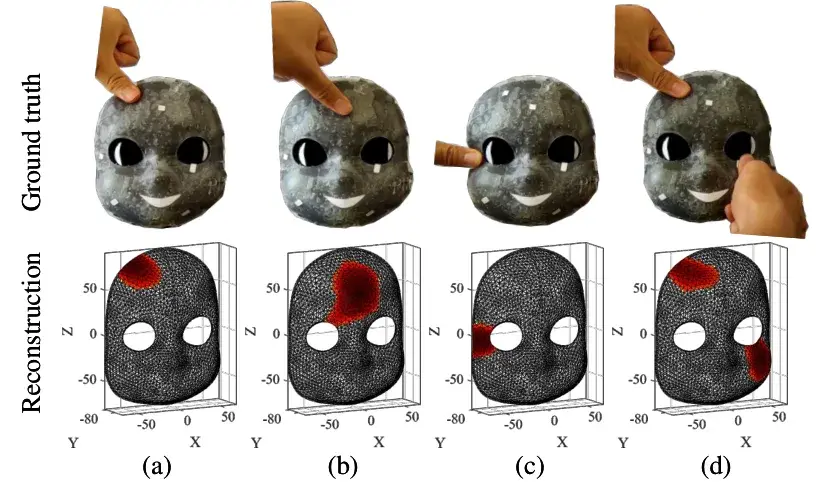
On a lab bench at the Czech Technical University in Prague sits a 3D-printed robot face. Gray, two big round eyes, an arc for a mouth. When a finger presses its forehead, cheek or chin, a red blob lights up at the same spot on a 3D reconstruction on screen. The face doesn't smile harder, doesn't blink. But it knows exactly where it was touched.1
Look at what this demo leaves out. Under the mask's surface there is no sensor matrix, no web of thin wires, no distributed readout electronics. One continuous layer of conductive rubber 0.8 mm thick, boundary electrodes assembled by hand, and an algorithm that reconstructs the position of the press from electrical currents. That's the whole stack.1
To appreciate what that "whole stack" means, consider who wrote the paper. Two of its authors, Matej Hoffmann and Alessandro Roncone, spent years at Italy's IIT lab, where the iCub was built, working with the robot's capacitive-triangle skin, roughly 4,200 measurement points across the body in the version they studied.5 A third, Hyosang Lee, co-authored a hydrogel robot skin published in Science Robotics in 2022, already built on the same tomographic imaging idea.10 This printed skin comes from people who spent years grinding on the other solution and eventually changed methods; they know the problem from the inside.
The paper, posted to arXiv on August 3, 2026 and submitted to the IEEE Humanoids conference, describes a conformal tactile skin made by 3D printing, validated on a flat surface, on a curved surface, and then on the iCub's face.1 Hackaday picked up the signal on August 24.2 What follows is a process reading: how the skin is made, what it actually senses, what it doesn't, and what this change of method says about how robots get built.
Thousands of taxels
A humanoid has roughly two square meters of surface to cover, about the same as a human body.6 The classic way to give it a sense of touch is to attach as many point sensors as possible, called taxels, then read them all.
The iCub shows what this looks like at the scale of a real robot. Its skin is organized into patches: eighteen on the robot, one per hand, two per forearm, four per upper arm, four on the torso. Each patch carries up to sixteen flexible triangular modules, each triangle holding ten capacitive sensors plus two thermal pads. Triangles connect to each other on a flexible circuit with no extra wiring, and a microcontroller reads the whole thing over a CAN bus.3 The robot's spec sheet lists more than 3,000 tactile sensors at 8-bit resolution refreshed at 40 Hz;4 the most heavily equipped versions reach around 4,200 taxels, counting fingers, palms, arms and forearms, torso, legs and feet.5
This system works, has been documented for over fifteen years, and produced real results, including calibrating the robot's kinematics through self-touch.5 But it carries a structural cost everyone in the field knows: every sensor must be manufactured, positioned on a given geometry, connected, read, and calibrated to its exact location. A review published in early 2026 in Proceedings of the IEEE puts the remaining problem right in its title, wiring and data management for large-scale skins.7 Above all, none of it transfers. The iCub's skin doesn't move to another robot, because it was drawn for the iCub. Every new morphology starts from zero.
That is the problem this team attacks, and the choice they make is radical: delete the point sensors.
Sensing through current
The borrowed technique is electrical impedance tomography, EIT. It is a medical imaging method: inject a weak electric current into a conductive volume, measure the voltages appearing at surface electrodes, and reconstruct a map of the internal resistance. In clinics it is notably used to monitor lung ventilation without a scanner.8
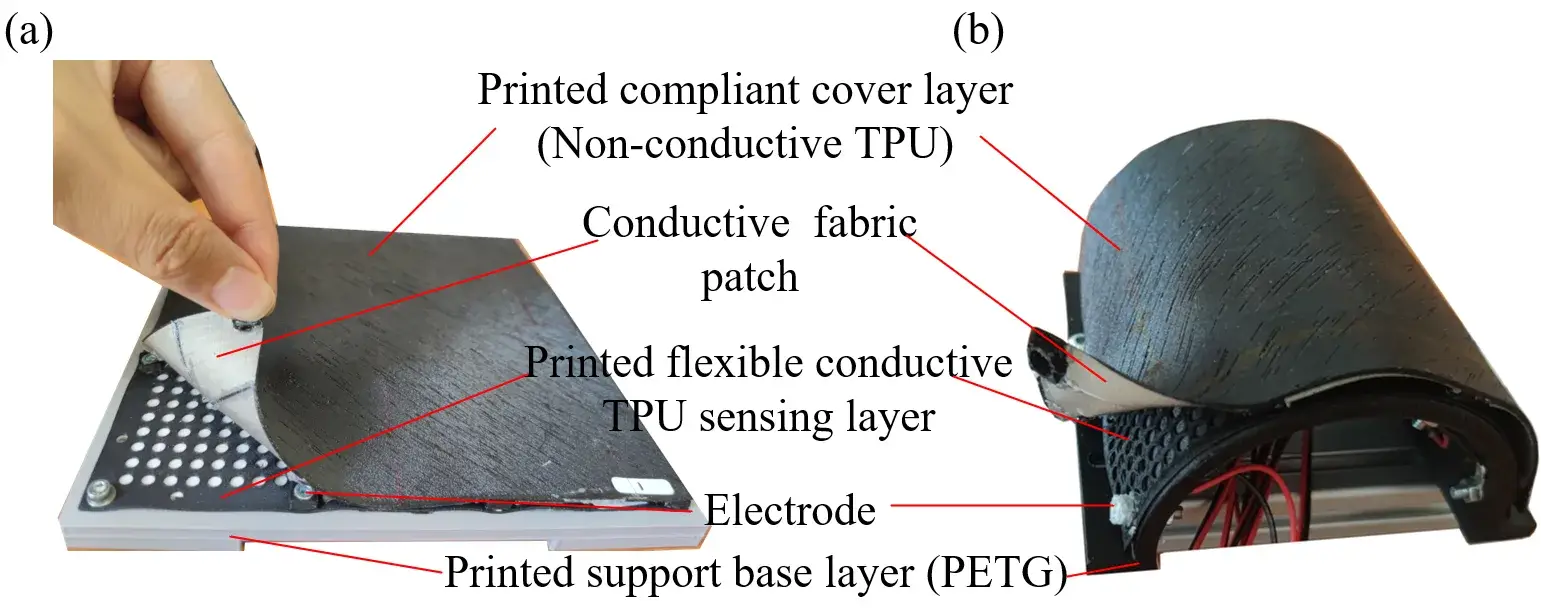
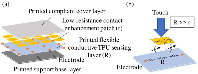
Translated onto a skin, the idea becomes almost trivial to state. That is its charm. The conductive rubber layer forms a single continuous electrical volume. When you press somewhere, the pressure locally increases the contact area between a conductive patch and that layer, local resistance drops, and this conductivity dip shows up as a perturbation in the voltages measured around the perimeter. The algorithm works back from the perturbation to its position.1 Maya Posch's summary on Hackaday is accurate: the whole thing behaves like a resistive touch screen in skin format.2
Two technical choices matter here. First, the sixteen electrodes don't all sit on the edge: they are laid out in a 4×4 grid across the whole surface, center included, because tomography sees the middle of a large domain poorly when it only measures at the boundary.1 Second, the reconstruction skips trained neural networks entirely. It runs a classical one-step Gauss-Newton solver whose matrix is precomputed offline from a finite element model of the sensor. That model itself comes from the CAD geometry of the part, imported into EIDORS, the open-source tomographic reconstruction toolkit.19 The loop closes: the CAD file used to print the skin also builds its readout model.
Four printed layers
The fabrication section reads the most like a maker recipe in the whole paper, because it is one.
The sandwich goes, bottom to top: a rigid printed PETG base that sets the geometry; a 0.4 mm sensing layer of conductive TPU; conductive fabric patches bonded on the outer side, where the presses land; and a very soft TPU cover that protects everything.1 No exotic materials. The conductive TPU is an off-the-shelf filament, Recreus Conductive Filaflex. The conductive fabric is shielding textile sold by the meter, Würth WE-TS 33025. All three layers go through a standard FDM printer, and the paper publishes the settings: 250 °C nozzle and 15 mm/s for the conductive TPU, 235 °C for the soft cover, 230 °C for the PETG.1
What got eliminated teaches more than what made the cut. The team compared three materials for the contact patches: printed conductive TPU, conductive spray paint, and conductive fabric. Counterintuitively, the printed patch produced the weakest response and the fabric the strongest; the spray responded early at low forces but plateaued, likely because of uneven coating on the rough printed TPU surface. The practical takeaway: what matters is a very low-resistance patch facing a high-resistance sensing layer.1 The fabric wins, and it cuts with scissors.
Same logic for thickness. A 0.2 mm layer produces a stronger signal than a 0.4 mm layer, but it prints badly and tears during handling. The team settled on 0.4 mm, a stated compromise between sensitivity and printability.1 That kind of trade, signal versus manufacturability, isn't buried in the abstract: it gets a full results section, which is exactly what makes the paper reusable by anyone other than its authors.
Useful holes
One detail in the file goes against every instinct: to make this skin more sensitive, the team punched holes in it.
The sensing layer is printed with a calibrated grid of holes, roughly 27% porosity on the flat prototype and 38% on the curved one. The mechanism is the same as for thickness: holes raise the effective resistance of the layer, which makes the local perturbation created by a press more visible in the measurements, without having to print any thinner. Tests show that going from 0% to 21% porosity already increases the response, but going from 21% to 38% adds nothing measurable.1 Moderate porosity is enough; beyond that it's wasted material.
It's an inversion worth remembering for anyone working with conductive materials: here, sensor sensitivity is tuned with geometry, not chemistry. No new formulation, no material to synthesize. An infill parameter in the CAD file.
What the skin feels
So what does it actually pick up? The numbers exist. They carry good news and bad news.
On the flat 150 × 150 mm skin, a motorized stage presses at predefined points with a 15 mm cylindrical indenter, at forces from about 1.5 N to 16 N. At moderate force, mean localization error drops to 7 ± 3.5 mm, with a median of 6.7 mm and a 90th percentile of 10.8 mm over 36 valid points. At the highest forces, mean error falls to 6 ± 3 mm.1 For a skin with no discrete sensors at all, that's the order of magnitude of a finger pointing at a map. Short of instrument precision, and plenty to know where you were touched.
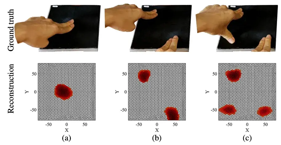
The skin also distinguishes multiple simultaneous presses. One, two, three fingers resting at separate spots produce three separate blobs in the reconstruction, with growing blur as contacts multiply, a stated consequence of the physics: EIT is a diffusive imaging method with intrinsic spatial resolution limits.1
The test that matters for robotics is the curved surface. The U-shaped prototype, 40 mm radius and 100 mm length, took 18 presses spread over its surface, applied by an indenter mounted on the wrist of a Kinova Gen3 robot arm. Mean error: 6 ± 4 mm, ranging from 1.5 to 14.4 mm depending on position.1 Same stack, same readout chain, different geometry: that transferability is the paper's real claim, more than the precision number itself.
The force response exists but is nowhere near linear: the reconstruction reaches half its maximum response around 3.8 N, 80% around 8 N, 90% around 12 N, then saturates.1 The paper says it plainly: the reconstruction carries information about press intensity, but reliable force estimation would need position-dependent calibration or learned compensation. The skin knows where you touched it, roughly guesses how hard, and cannot weigh the press.
Blind to caresses
The other end of the curve deserves a read, the end the paper's abstract doesn't highlight in bold. At the three lowest force levels of the experiment, mean localization error is 25 ± 30 mm. In other words: under a light press, the reconstruction is so noisy that the average error approaches three centimeters, with huge spread.1
That's the inverse of a human fingertip, which reads surface details far finer than three centimeters. I find this inversion more interesting than the performance numbers: this skin is built for frank events, a collision, a handshake, a body-weight lean, not for exploring a surface with the tips of its sensors. For a humanoid torso or arm, that bias is probably the right one. For a hand it isn't, and nobody claims otherwise.
The authors list the limits themselves, without varnish. The force response saturates and needs calibration. Spatial resolution is bounded by the diffusive physics of the method. And the iCub face experiment stays qualitative: manual touches at representative spots, no systematic campaign.1 A prototype that opens a door. The product will have to wait.
The iCub lineage
What gives this paper its depth is the trajectory of the people who wrote it, and it can be reconstructed entirely from public sources.
In 2014, Alessandro Roncone, Matej Hoffmann and their IIT colleagues published an ICRA paper on calibrating the iCub's kinematics through self-touch: the robot touches itself, locates the contact points on its roughly 4,200-taxel skin, and derives a correction of its own body model. The robot's forearm alone carried two patches of 84 and 192 taxels.5 Twelve years later, the same two names sign the printed skin, Hoffmann in Prague, Roncone at the University of Colorado Boulder.1 The career loop is visible: the people who calibrated a taxel-based skin now draw skins that have none.
The third thread runs through Hyosang Lee. In 2022 he co-authored the Science Robotics paper on a biomimetic hydrogel-and-elastomer robot skin, also based on impedance tomography, complemented by passive acoustic tomography: 32 electrodes and 25 microphones over a 20 × 20 cm surface, able to localize caresses, tell a tap from a press, repair itself after a cut, and demonstrated on a cosmetic prosthesis.10 Between that lab-built hydrogel skin and the 2026 printed TPU skin, the continuity is direct: same physics, same algorithm family, but a material that moves from hand-assembled hydrogels to 3D printing on CAD geometry. Lee is now in Eindhoven, the paper's third institution.1
In between, another team had already shown EIT on a humanoid face, but with hybrid fabrication: a printed support, then spray coating, molding, manually placed conductive patches and electrodes.11 The specific contribution of the 2026 paper lives in that gap: the sensing layer itself is printed, on a curved geometry, with quantitative validation, after a first version presented at the ICRA 2026 workshop on large-area tactile skins.1
Electrodes by hand
The title of this section is nearly literal: what isn't printed is precisely the electrodes and patches, assembled by hand. The authors name it as the main lock before a "truly fully 3D-printed" sensor.1
The iCub face shows where the method's frontier runs. On that strongly curved geometry, the 0.4 mm conductive layer proved impossible to print reliably with FDM: the team had to switch to a solid 0.8 mm layer, replace the soft cover with an SLA resin part, and assemble everything else manually.1 Scaling up, torso, hands, full head, assumes automating the whole chain, from CAD to finite element model to electrical interfaces. It's listed as future work, meaning not done.1
The other camp also deserves its due, because it hasn't disarmed. In 2025, a Brigham Young University team presented a piezoresistive fabric skin architecture chaining 8,192 taxels across one square meter at over 50 frames per second on a single daisy-chained SPI bus, with a striking demo: without tactile feedback, the robot's open-loop trajectory slowly crushes a cardboard box; with it, the same motion becomes a stable, gentle grasp.12 The taxel route, properly wired, is very much alive. The real debate is less tomography versus taxels than matching the philosophy to the body part: continuous reconstruction for large forgiving surfaces, dense sensors where precision pays.
From mask to body
What this paper gives the rest of the world is a pipeline more than a sensor. A CAD geometry goes in one end, a printed skin with its reconstruction model comes out the other, and the same sequence replays on another part without redrawing a single sensor. That shift from object to process is what separates this work from one more demo, and it explains why a site like Hackaday cares about a fundamental research paper.2
For a lab or a hacker with an FDM printer, the entry barrier is surprisingly low: a commercial conductive filament, a shielding textile, an open-source solver, and print settings published in black and white.19 The real difficulties sit elsewhere, in the electromechanical characterization and in building the reconstruction model, and the paper documents both. The supplementary video shows the touches on the face.1
The follow-up list from the authors is short: printed electrical interfaces, integrated wiring, automatic model generation from CAD, force-controlled testing on freeform surfaces, durability and hysteresis characterization, integration with whole-body controllers for contact anticipation, impact mitigation and safe physical interaction.1 Every line on that list is a project, not a week of work.
A robot face that knows where you touched it is still a lab object. But the trajectory is legible, and it runs one way: fewer sensors, more skin, and skin manufactured like any other mechanical part, from the same CAD file. Twelve years after calibrating a robot by making it touch itself with 4,200 taxels, the same researchers print touch directly onto its face. The next logical step is a torso. It has been announced. It has not been printed.