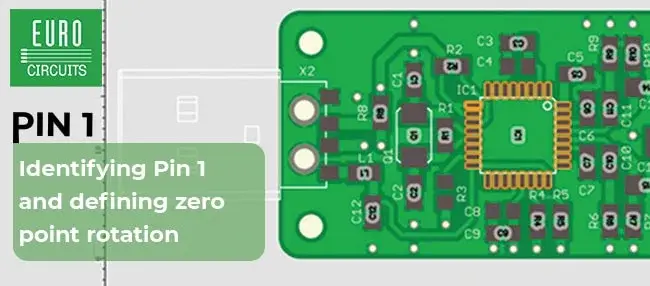
A QFN sitting on a table has no magnetic north: it has a Pin 1, package geometry and perhaps a molded marker, but its 0° angle is not a physical truth.
Zero appears when a CAD library decides how to draw the package; the pick-and-place export reuses that orientation to say “U17 at 90°,” and the assembler eventually has to convert the number into real motion even though the component arrives in tape, tray or tube with its own practical orientation.
When all three stages share a convention, nothing interesting happens, whereas two tools assigning different meanings to zero can make 90° perfectly precise and perfectly wrong.
Invented zero
IEC devoted an entire standard to this small problem. IEC 61188-7:2017 establishes a consistent technique for describing component orientation and land-pattern geometry so data can move more reliably between partners in the electronics chain.1
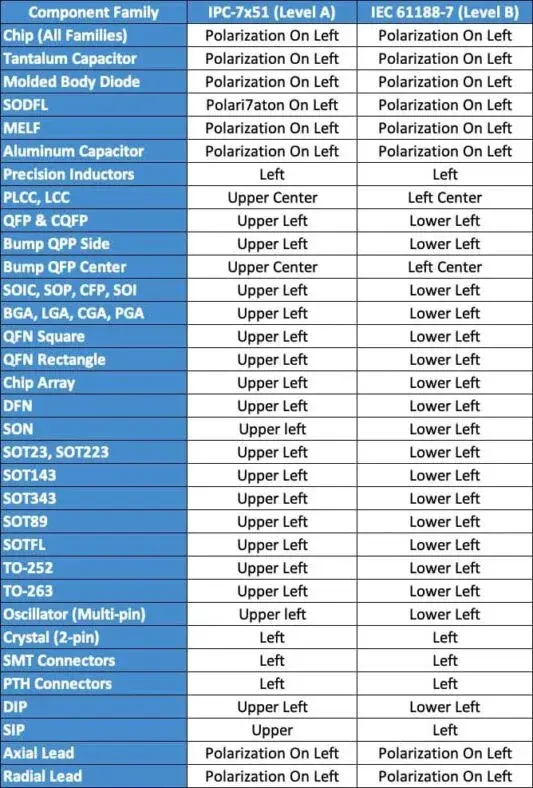
The 2017 edition supports two orientation levels and identifies Level B as preferred for new libraries.1 KiCad's Library Convention takes a different practical route, generally asking for Pin 1 in the upper-left corner of a footprint while documenting exceptions for two-terminal parts, connectors and packages whose first pin sits in the middle of one side;2 that is the IPC-style zero convention used by the official KiCad libraries.
Eurocircuits uses IEC 61188-7 in its own assembly flow, where the multi-pin orientation it documents places Pin 1 at the lower left for the level it follows.3
Neither choice makes the other geometrically impossible; they simply select different zeros for describing the same package.
The chain
The angle in a placement file is useful only once its starting orientation is known: a package drawn at zero in the library may be rotated by 90° on the PCB, exported beside its X/Y coordinates, and then presented to the factory machine through a feeder whose incoming orientation depends on the manufacturer's packaging.
By the time the part reaches the machine, four references have to remain aligned: library zero, board rotation, incoming package orientation and machine convention.
An assembler can correct a rotation easily when the convention is known; the manual work begins when every footprint seems to arrive from a different coordinate system.
Eurocircuits includes a check in its Assembly Checker that can flag a mismatch between expected Pin 1 and the submitted design.3 That tool does not prove that IEC is the world's only valid orientation; it tries to catch the moment when the contract presented to its assembly process becomes ambiguous.
Pin 1
Pin 1 gives many package families a stable physical reference, although that reference alone does not answer the separate question of what the CAD library calls zero degrees.
A BGA may mark A1 in a corner, an SOIC may have a notch or dot, and a polarized component identifies one electrode. A library still has to decide where that reference sits inside its coordinate system.
KiCad's current general rule places Pin 1 at the upper left; two-terminal parts put Pin 1 on the left, multipurpose connectors are normally horizontal, and packages whose first pin lies in the middle of a side receive specific treatment.2
The KLC also begins with an important qualification: its requirements are guidelines, and a manufacturer datasheet should take precedence when there is a genuine conflict, unless a documented reason justifies an exception.2
That caveat matters because a library rule stops helping when it forces a specific package to be redrawn against its own documentation.
Mixed library
The dangerous case is less IEC versus IPC than a library that never chose one convention consistently.
A library accumulated over years can contain footprints drawn manually, imported from manufacturers, generated by tools or copied from other libraries, with each source potentially starting from a different orientation.
Nothing necessarily looks wrong on the schematic or even the PCB, because a designer can rotate the package until the drawing matches the datasheet, the traces reach the correct pads and the board appears electrically sound.
The contradiction can stay hidden until placement export. If some footprints were built from another zero, the Rotation column suddenly contains several reference systems under one field name.
That is unusually unpleasant library debt because it does not break electrical design; it breaks translation from design into machine motion.
Decide once
IEC 61188-7 exists because a global CAD library cannot depend on “the orientation is obvious when you look at the package.” Its stated purpose is consistent capture and transfer of component and land-pattern data between trading partners.1
For a team, the robust workflow looks less like another CAD plug-in and more like five boring decisions made explicitly:
- choose a zero convention for new footprints;
- document it in library rules;
- inspect imported footprints instead of assuming they use the same zero;
- export placement data whose rotation convention is known;
- give the assembler enough information to translate that zero into its feeder setup.
KiCad does this at public-library scale through the KLC, which sets general conventions and documents exceptions.2 Eurocircuits does it at the other end of the chain by publishing the convention used in its flow and checking submitted data for orientation mismatches.3
The handoff then becomes an explicit contract rather than a guess made on the assembly floor.
Portable zero
The lesson extends beyond circuit boards.
Whenever an object moves between several programs, machines or companies, a local value starts to look like a universal fact: the origin of a 3D model, positive rotation direction, the datum of a CNC setup, a robot axis, camera orientation.
A useful convention does not need to feel geometrically intuitive; it needs to remain stable, documented and translatable at system boundaries.
IEC and KiCad can therefore place Pin 1 differently without either one discovering a new north. Their apparent disagreement points to the same rule: when a machine has to read your drawing, zero deserves as much definition as the shape itself.