A circular saw does not have to become a robot to enter a digital fabrication workflow.
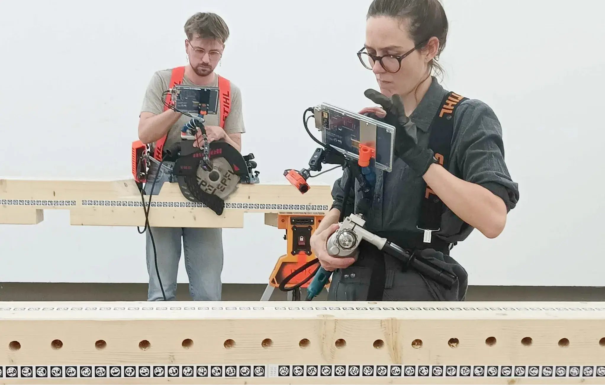
At EPFL's IBOIS Laboratory for Timber Constructions, an ordinary handheld power tool can instead receive a camera, a small screen and a portable computer. The carpenter still holds the saw. The carpenter still decides when to cut. What changes is the layer between the CAD model and the hand: the timber is mapped, the tool is tracked, and the display shows whether the blade is in the right place, at the right angle and at the right depth.1
That sounds like a small distinction until you look at how digital timber fabrication is usually organised. The most precise workflows tend to move work toward CNC machines or robotic cells. Augmented Carpentry moves in the opposite direction. It tries to bring the digital model back to the tools already found in the workshop.
The research programme ran from 2022 to 2025. Its final system is open source, several components were published separately, and the 2025 synthesis paper evaluates the complete chain on one-to-one timber structures instead of stopping at an attractive demonstration.1 2 3
That last part matters. An augmented-reality prototype can look magical for thirty seconds. The useful question starts when the camera loses its map, the beam gets longer, sawdust fills the frame, the tool vibrates, the workpiece changes shape after a joint is cut, and someone still has to make the next cut correctly.
Augmented Carpentry is interesting because the answer is neither “everything works” nor “this is a toy.” The project lives in the much less photogenic space between those two positions.
The familiar tool
The hardware stack is deliberately ordinary.
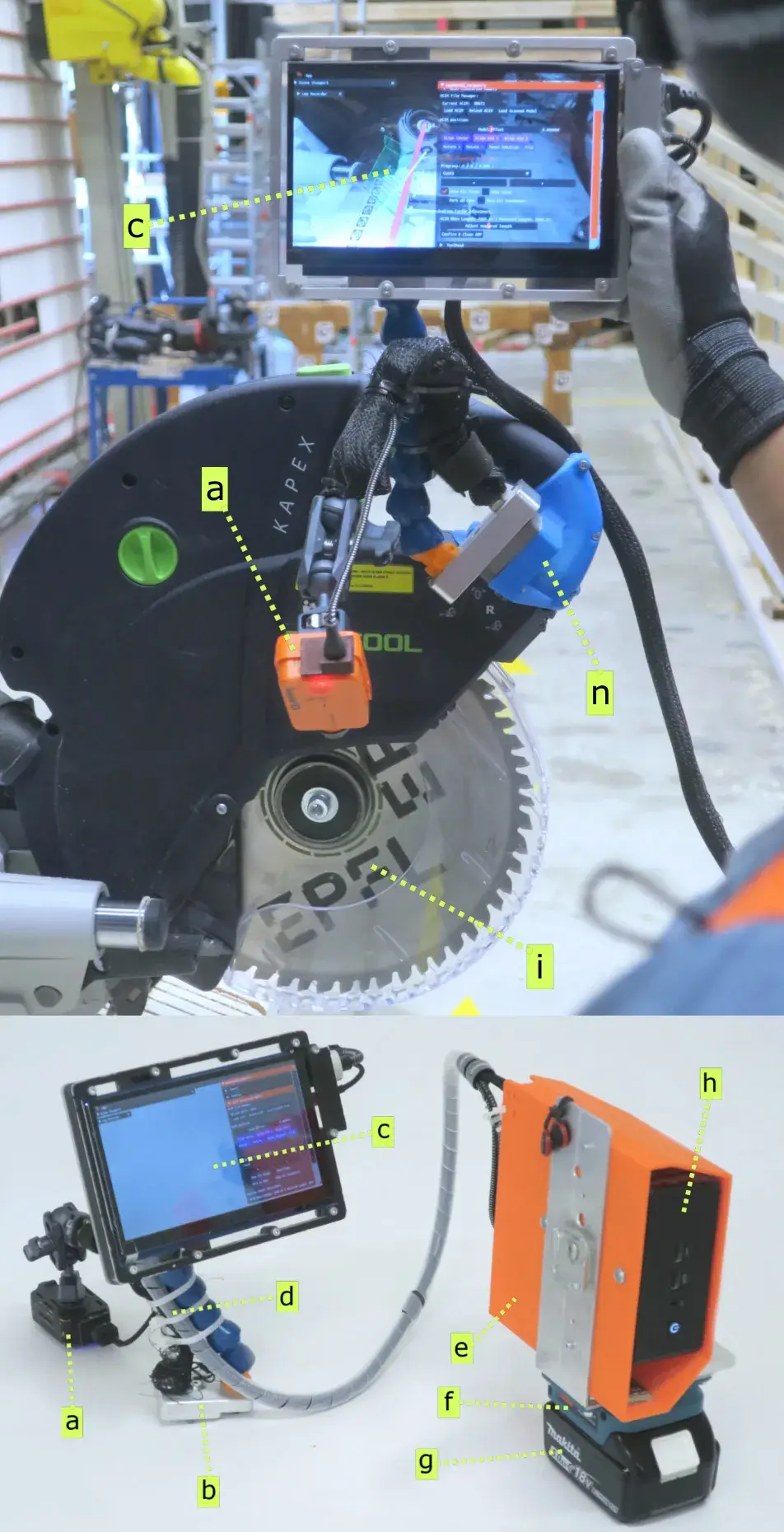
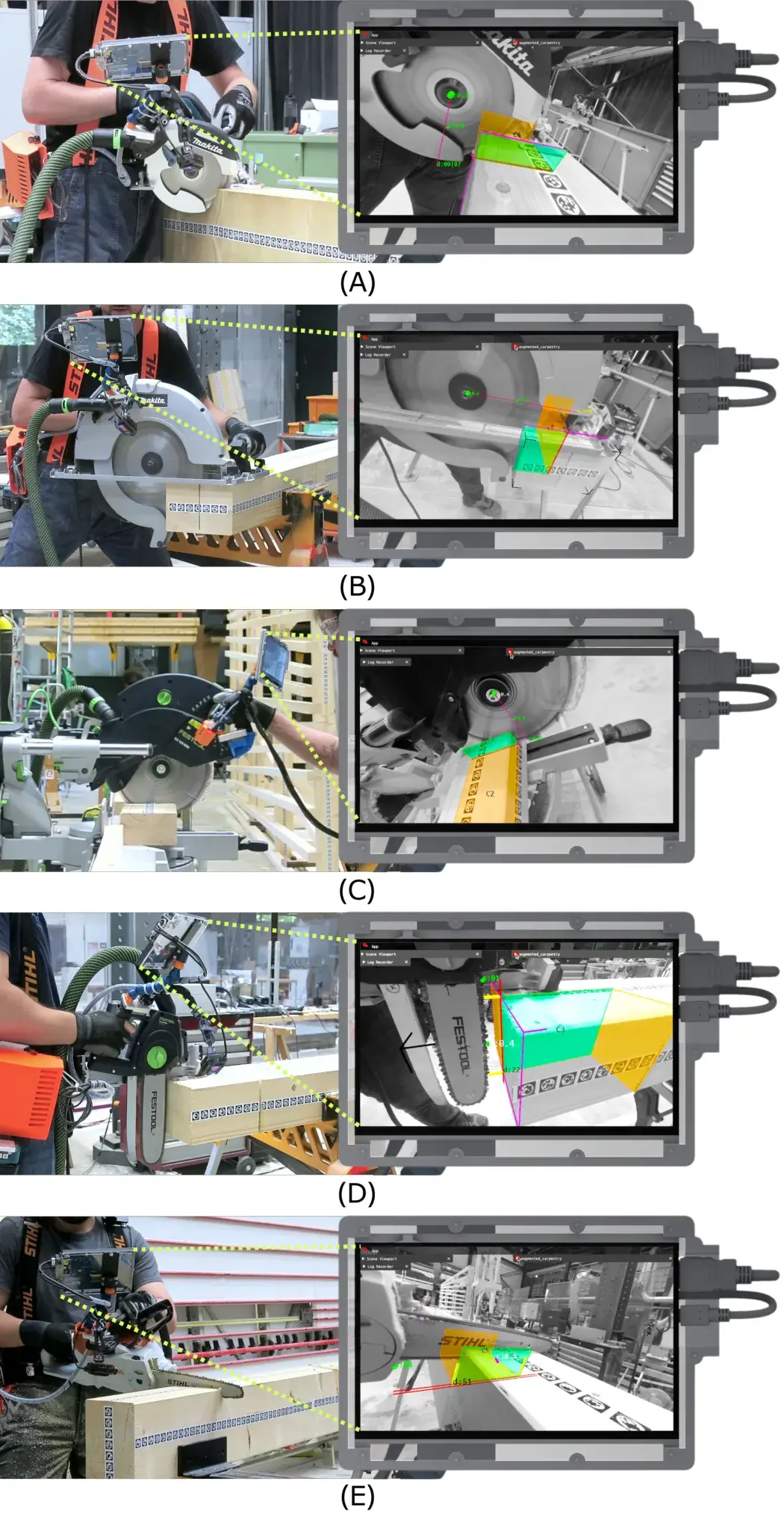
In the system described in the 2025 paper, a retrofitted power tool carries a RunCam2 1080p monocular camera, a seven-inch touch display, articulated mounts and a tool-specific 3D-printed bracket. A portable Intel NUC handles the vision pipeline and the interface. The camera-display module can move between tools through a magnetic mount, while each tool keeps its own bracket and a calibrated digital representation of the tool head.1
The team integrated several circular saws, a miter saw, drills with interchangeable bits and even a chainsaw. The point is not that the tools become interchangeable. The idea is that the expensive layer of sensing and computation can be shared while the part that actually cuts remains recognisably workshop hardware.1
That is a very different choice from designing a machine around the digital process.
A CNC machine knows where its spindle is because it controls the machine axes. A robot knows where its tool is because the position of every joint belongs to the control system. A person holding a circular saw breaks that clean relationship. The system has to observe the tool from the tool itself and continuously estimate where the blade sits relative to a piece that can move, rotate, collect dust and change geometry as material is removed.
The project therefore spends a surprising amount of engineering on a question that almost disappears inside a CNC machine: where exactly are the tool and the workpiece right now?
Map the beam
The timber is not treated as a passive block underneath a hologram.
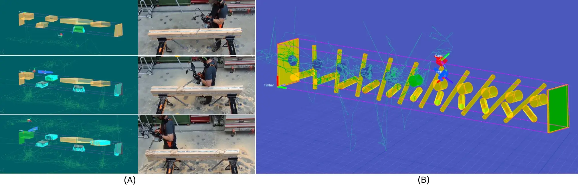
Augmented Carpentry begins by mapping the workpiece. Fiducial markers are placed along the beam and recorded by the camera. The system builds a local map and then locks the digital execution model to that physical geometry.1
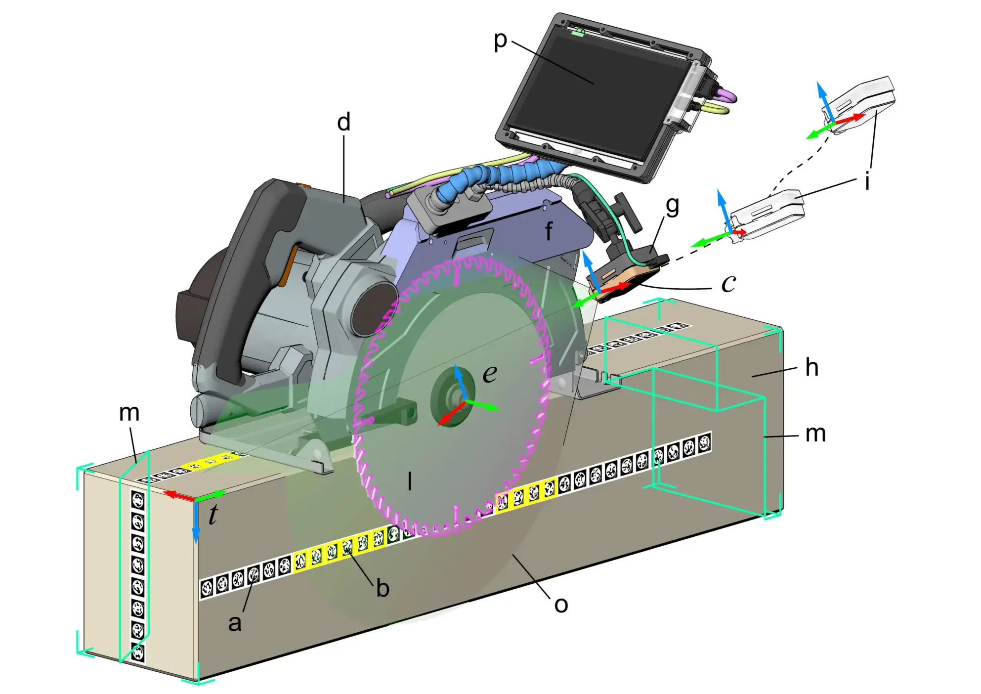
That lock supports everything that follows.
If the overlay drifts by a few millimetres, the nicest interface in the world becomes only a very convincing way to cut in the wrong place. The digital model therefore cannot float “roughly” over the timber. It has to stay attached to the object while the camera moves with the tool.
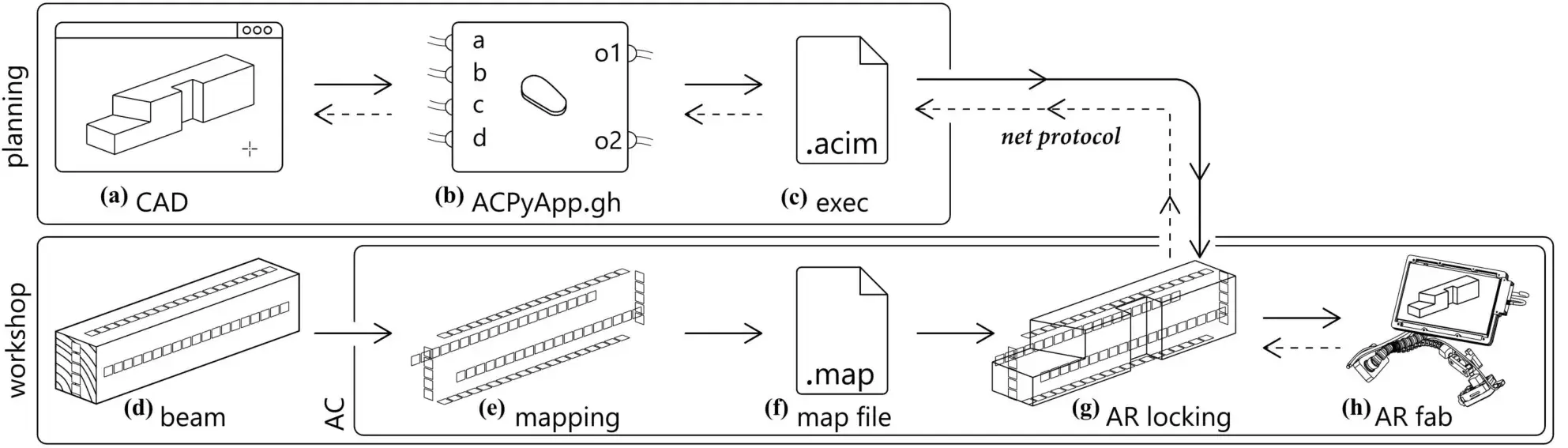
The dataflow described in the paper looks more like a manufacturing pipeline than a conventional AR app. The model is exported from the design environment. The real beam is tagged and mapped. The execution model is loaded and associated with that map. Only then can the software display guidance for a specific operation.1
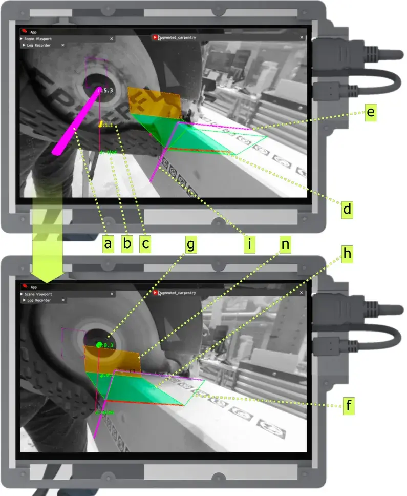
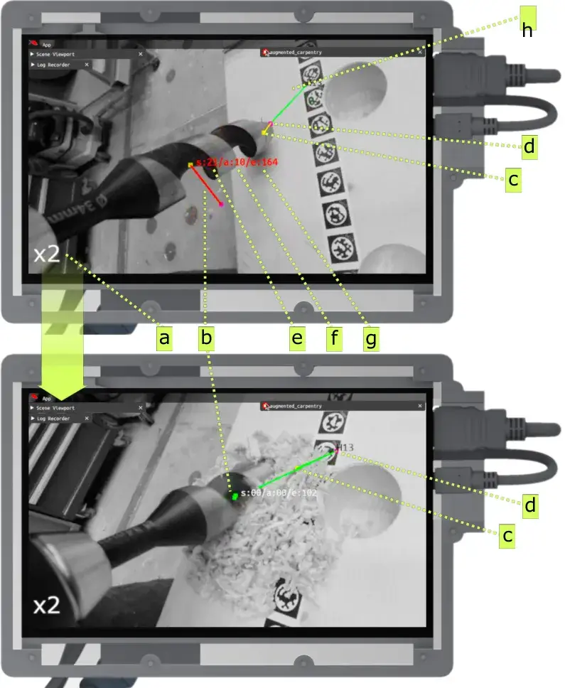
The visual result remains simple. For a saw cut, the operator gets cues for position, orientation and depth. For drilling, the screen shows whether the drill angle and entry point match the hole defined in the model. The person moves until the indicators align, then performs the operation.1
No robotic arm comes in to correct the motion.
That is not a missing feature. It is the thesis of the project.
Computation as jig
The authors describe Augmented Carpentry as a feedback system rather than a controller that imposes a rigid sequence. The software exposes measurements and alignment information, but the user decides how and when to act.1
The choice becomes clearer when compared with Shaper Origin, the commercial descendant of earlier research into computer-guided handheld tools. Shaper Origin is still held by a person, but its router spindle can make small local corrections while the operator follows the broad path. The Augmented Carpentry paper explicitly cites that lineage, then tackles a different problem: timber-construction operations on larger components, using multiple ordinary tools and an execution model that is aware of the workpiece itself.1
The distinction is subtle but useful.
One path asks how much cutting motion a handheld machine can correct. The other asks how much computational precision can be added without taking the motion away from the operator.
That leaves more responsibility with the person and therefore more variability. In exchange, each operation does not require turning the tool into a new specialised mechatronic machine.
You can almost reduce the experiment to one question: can computation become a jig?
A physical jig encodes a decision in a piece of material. It constrains or guides movement because its shape constrains the tool. A shop drawing encodes the same kind of decision in dimensions, and the craftsperson translates those into marks, references and fixtures. Augmented Carpentry tries to move both functions into a live overlay: the CAD model becomes the reference, the camera keeps it attached to the timber, and the display tells the operator how far the tool is from the intended operation.
The carpenter still supplies force, dexterity and part of the judgement.
The computer supplies a continuously updated answer to the question: “where should this tool be?”
No headset
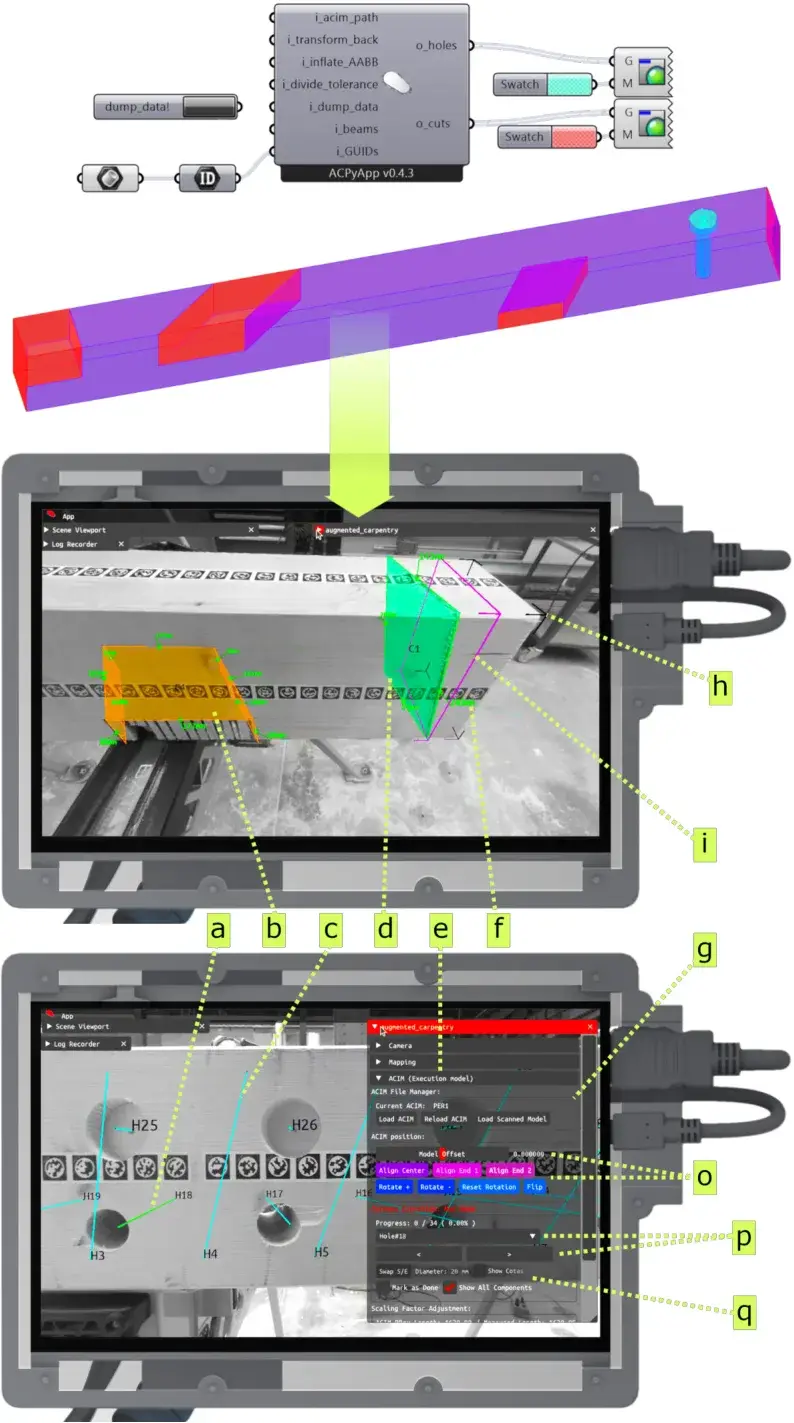
A headset seems like the obvious interface for an augmented-reality project. The researchers tested related approaches in earlier work, including HoloLens-based systems, then explain why the final version does not start from that assumption.1 4
A headset adds another localisation problem. The system has to know the pose of the headset, the pose of the tool and the relationship between both and the workpiece. Calibration errors accumulate. Lighting can disturb tracking. Markers have to remain visible from the operator's head. And you end up putting delicate display hardware on the face of someone using a saw or drill.
The final version instead mounts the camera and display on the tool. The camera therefore keeps a stable relationship with the cutting head, and the user looks at a familiar screen rather than a floating hologram.1
It is less cinematic.
It is also a useful reminder that the most futuristic interface is not automatically the interface with the fewest failure modes.
The same pattern appears across the project. The team accepts more setup work in order to reduce ambiguity during execution: printed mounts instead of a universal attachment, fiducial markers instead of pretending markerless tracking is solved, explicit mapping of the beam instead of eyeballed alignment, precise visual cues instead of automatic interpretation of what the operator ought to do.
The system looks advanced because it uses computer vision. A large part of its engineering is really about refusing invisible approximations.
Scan the result
The evaluation campaign is the strongest part of the project.
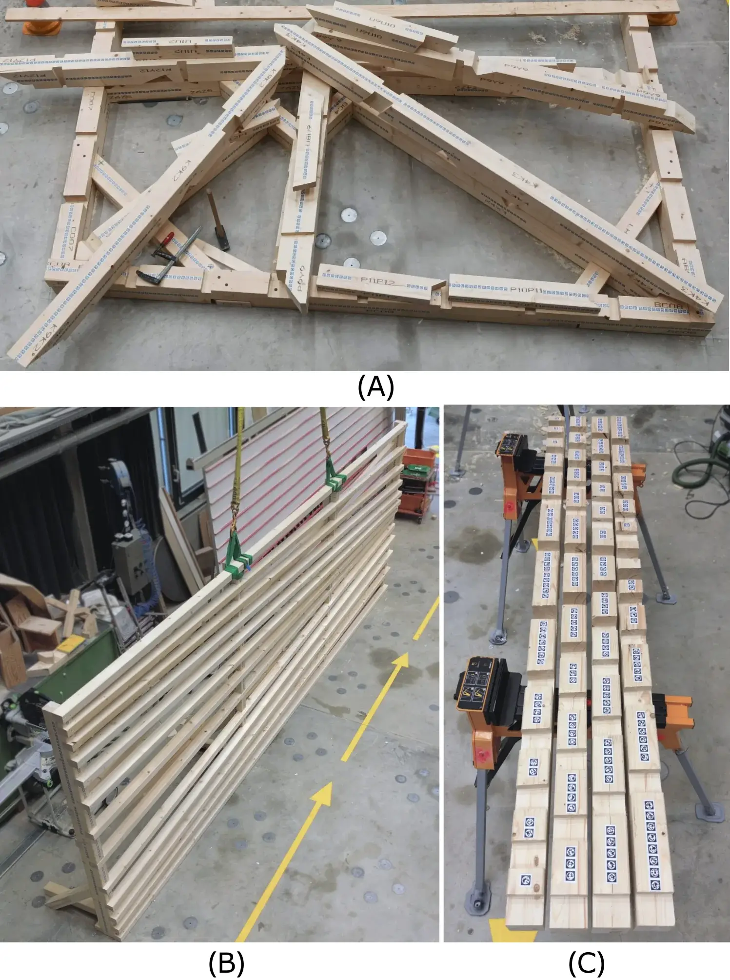
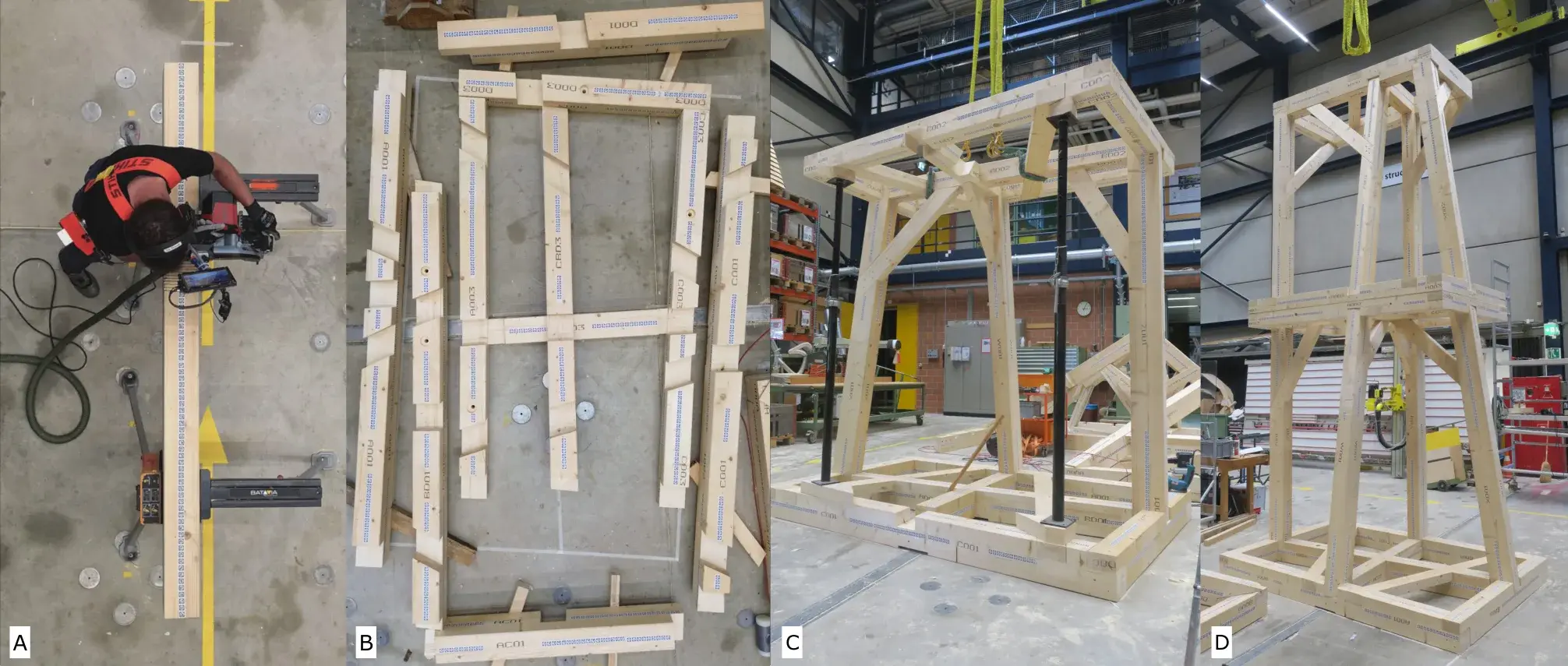
The 2025 paper reports 166 joints fabricated on 57 white-spruce elements ranging from 0.5 to 3.8 metres. The tests use one-to-one structural mock-ups rather than small tabletop specimens. The fabrication team consists of two people: an inexperienced trainee and a mid-level carpenter.1
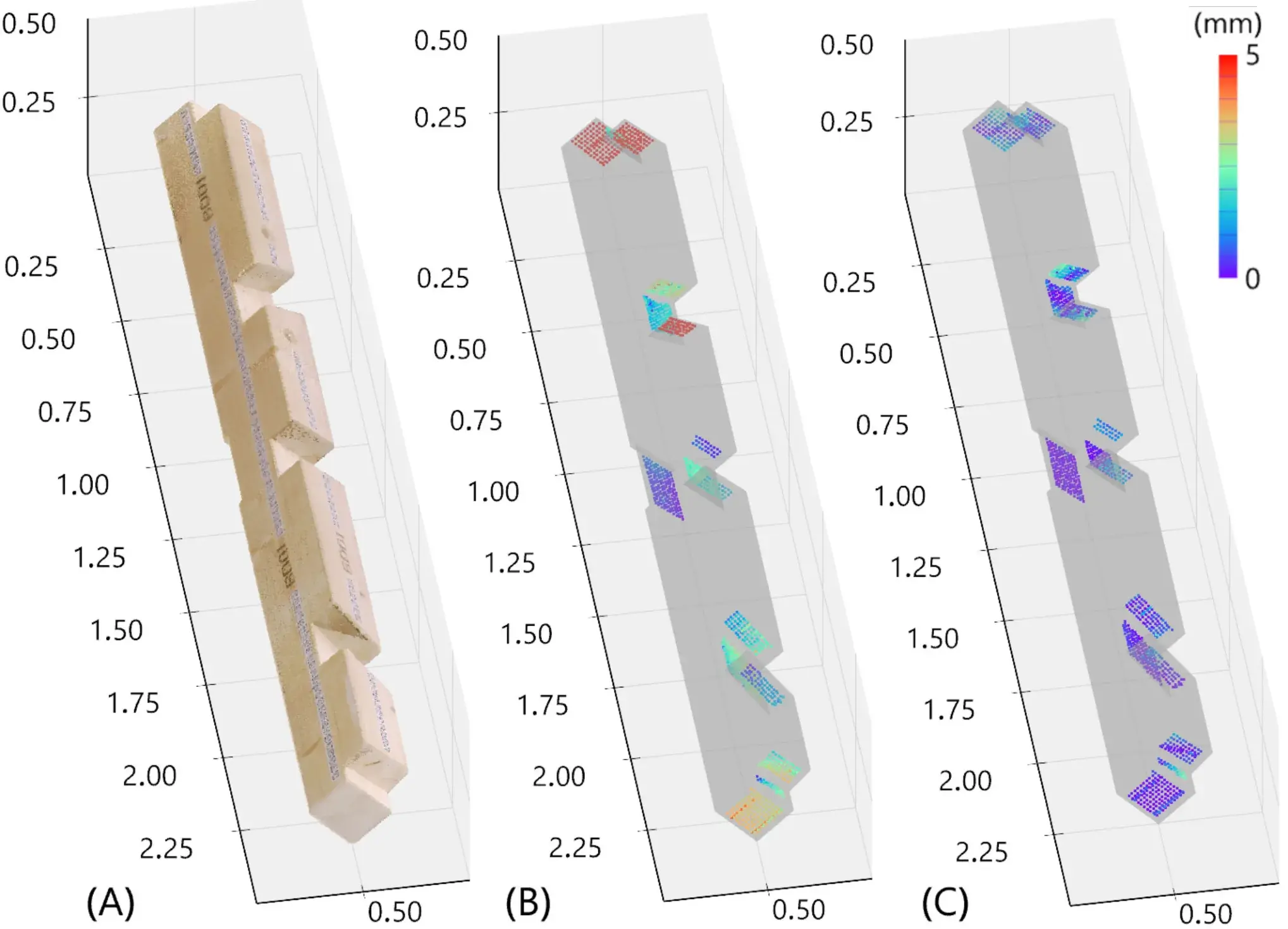
After fabrication, the researchers scanned individual beams and then assembled structures. They registered the resulting point clouds against the CAD execution models and measured where the fabricated geometry diverged from the intended geometry.1
That is much more useful than asking whether the overlay “felt accurate.”
For joint localisation, the paper reports a mean error below 3 mm overall. When the initial prototype with beams longer than three metres is excluded, the average error improves to 2.3 ± 1.3 mm. The data also exposes the weakness: error increases with element length, and mapping the longest pieces became unreliable enough to produce distorted maps or complete failures.1
The evaluation also separates execution errors. Mean sawing-angle error stays below one degree in the reported set. Drilling measurements show similarly small but real deviations in orientation and entry position.1
Those numbers do not mean “computer vision turns a novice into a precision carpenter.” The experiment is not designed to prove that, and it does not provide a control group that would justify the claim.
The result is narrower and more interesting: a camera-guided manual fabrication chain can carry a digital model into real sawing and drilling operations with millimetre-scale errors on full-size elements, until the assumptions behind tracking and mapping begin to fail.
That is a result you can actually argue with.
When wood disappears
Long timber exposes the central weakness of inside-out visual tracking.
A robotic cell can surround the working area with fixed references and external sensors. Augmented Carpentry wants the sensor to travel with the tool because that is what makes the system portable. The price is that the small local camera has to reconstruct enough of the workpiece to stay oriented.
The paper describes several problems. Longer beams make consistent mapping harder. Dust and wood chips add visual clutter. Vibrations disturb the camera. The geometry of the object changes as joints are cut. A camera close to the surface sees only a limited portion of the beam, and the wide-angle lens introduces its own distortion.1
There is an almost comic inversion here.
The software knows the CAD model with perfect mathematical precision, but it still has to recognise a real piece of wood through a camera attached to a vibrating saw.
This is where “software meets matter” stops being a neat phrase. Matter makes dust. Matter moves. Matter receives a notch that changes the silhouette the tracker knew five minutes earlier.
The project absorbs some of that complexity through markers and explicit mapping. It does not make the complexity disappear.
For beams longer than roughly three metres in the published campaign, mapping error becomes large enough to noticeably degrade joint localisation.1 That is a serious limitation because timber construction has the unfortunate habit of making things larger than a laptop screen.
A deployable system would therefore need better mapping, additional strategies for long pieces, complementary sensors, or a workflow that can recognise when localisation confidence has fallen below an acceptable threshold.
A green alignment indicator is useful only if the machine can also admit when it no longer knows where green should be.
Three years of layers
The final framework did not arrive fully formed.
A 2022 study tested a much narrower version of the idea: an ordinary electric drill integrated into an AR workflow for guiding angled drilling in timber.4 That stage already isolated the problems of tool pose, object registration and guidance before the team expanded the system to multiple machines.
In 2024, TTool focused on an even more specific component: detecting the six-degree-of-freedom pose of tool heads in the camera image. The final Augmented Carpentry system integrates that detector to calibrate the relationship between the camera and the blade, drill bit or chainsaw bar being tracked.1 5
Those intermediate results matter because they are not the final error of a fabricated part.
A blade can be located correctly and the joint can still be wrong because the beam map is wrong. The overlay can be correct and the human motion imperfect. Every individual joint can be acceptable and tolerances can still accumulate when the structure is assembled.
The final paper therefore measures the complete chain.
That progression, from a drill prototype to a tool-head detector to a full fabrication campaign, is why this subject earns a long article. It exposes all the layers between “we can track a machine” and “we can repeatedly fabricate a building component.”
A lot of research demos quietly die in that gap.
Augmented Carpentry walks into it on purpose.
The fabrication trail
One component is easy to overlook because it does not directly help make the cut.
Augmented Carpentry can record the 3D state of fabrication operations. The system stores tool positions and user choices, then can replay the sequence inside a digital environment.1
The workflow therefore becomes more than an augmented ruler.
A CAD file describes what the piece was supposed to become. A scan describes what it became. An execution log can describe how it got there.
The paper frames this as a path toward inspection, traceability and eventually forms of digital certification. That last step remains a proposal, not something demonstrated by the evaluation campaign. But the underlying capability is real: a deviation can be associated with a sequence of operations instead of being discovered only in the final geometry.1
For craft, that has two faces.
Documentation can transmit a process. It can help identify when a tolerance started to drift. It can let someone replay an operation rather than receiving only a finished object and a perfectly clean CAD model.
It can also turn manual work into an increasingly measurable stream of events.
The project does not settle what should be recorded, who should own those records, or whether the log becomes a teaching tool or a management tool. It only makes the question technically possible.
That is already more interesting than a vague promise about a “digital twin.”
Skill changes place
The tempting story would be to present Augmented Carpentry as a tool for people who do not know how to work timber.
The campaign does include an inexperienced trainee. But the paper does not properly compare novice and professional work, assisted and unassisted fabrication, or learning over time. It would therefore be wrong to conclude that a screen compensates for craft expertise.1
What the system mostly removes are some of the translations inside the chain.
With a traditional workflow, a digital model often becomes a drawing, then dimensions, then marks, then a jig or a tape-measure check. Every transformation requires skill and can introduce error. Augmented Carpentry tries to keep the model digital for longer and delay translation until the moment of action.
That does not make the action trivial.
The interface can indicate an angle. It does not necessarily choose the best way to hold the piece. It does not feel the grain. It does not spontaneously decide that a knot means the cutting order should change. In its published form, it cannot turn the full tacit knowledge of a carpenter into digital constraints.
The partially displaced skill is more specific: transferring, marking and maintaining certain geometric references between the model and the material.
Other skills become more important. The system has to be calibrated. The user has to understand what the overlay measures. Someone must recognise when tracking becomes suspicious. Enough judgement has to remain in the loop to avoid blindly following an interface that has tolerances of its own.
The user is not replaced by the machine.
The user becomes the last stage of a much more complex measuring instrument.
The missing invoice
The authors place the work in a specific industrial context. They contrast expensive, centralised automated cells with smaller construction companies that already own tools and rely on skilled labour.1
Retrofitting promises a middle route: keep existing machines, add sensing and computation, and obtain some of the benefits of a digital workflow without installing a complete robotic cell.
The intuition is plausible. The cost case is not yet complete.
The open sources consulted for this article detail the hardware components, but they do not provide a stable total cost for the kit, much less the full cost of workshop deployment including calibration, maintenance, training and time lost when mapping fails.
It would therefore be misleading to write that the system is “cheaper than CNC” as though there were already an industrial quote for a comparable installation.
What the sources do support is more modest: the architecture reuses existing handheld tools and concentrates new complexity in a layer of sensors, mounts and computation.1
That is a proposal for distributing investment differently, not yet an accounting proof.
The nuance is also what connects the project to several recurring IRZ themes: upgrading rather than replacing, extending an existing infrastructure instead of discarding it, and keeping human work in the chain when total automation is neither necessary nor obviously desirable.
Pencil versus camera
At first glance, Augmented Carpentry seems to place the craftsperson opposite the industrial robot.
The more interesting comparison may be elsewhere.
The system is competing with a pencil, a tape measure, a jig, a cutting list and all the small procedures that made manual work reliable long before anyone mounted a camera on a saw.
Those analogue tools have formidable qualities. They start instantly. They do not lose localisation. They tolerate dust. They do not require firmware. They are also good at transmitting a logic of work because their operation remains visible.
Augmented Carpentry therefore matters only when it does better than that stack of techniques in cases where geometry becomes complex enough that manual translation costs time, creates errors or requires one-off fixtures.
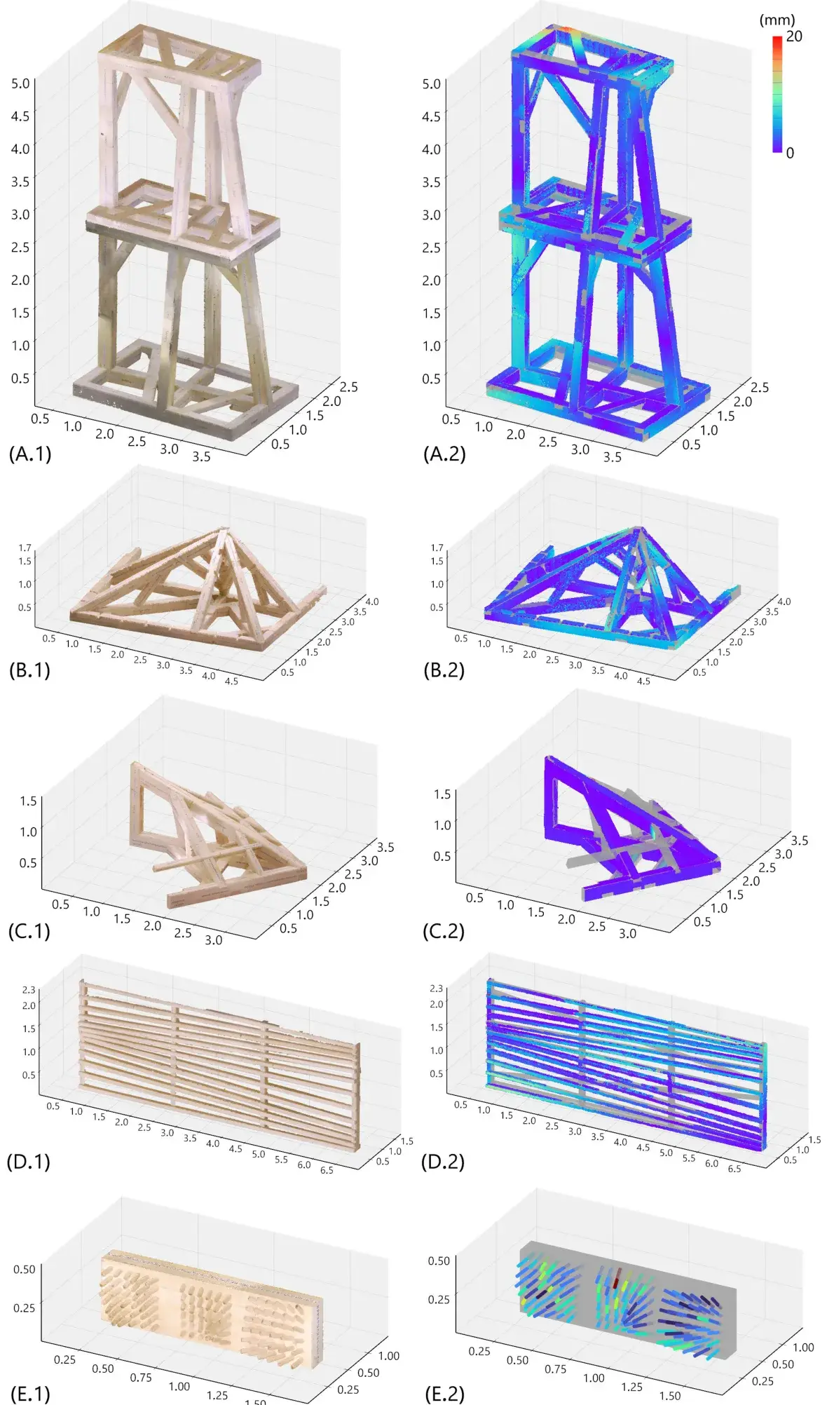
That is exactly what the team's parametric mock-ups illustrate: curved facades, irregular assemblies, series of operations in which the digital model can vary from one piece to the next.1
The potential gain does not come from a spectacular replacement of the human.
It comes from the fact that a computed model can change without requiring a new physical jig for every variation.
Software becomes interesting when repetition stops being perfectly repetitive.
The portable factory
The contribution of Augmented Carpentry is less futuristic than it looks.
The project does not discover computer vision. It does not discover augmented reality. It does not discover that a dimension can be shown on a display.
It assembles those pieces around one very particular design decision: the main machine remains in the operator's hands.
That constraint forces the researchers to solve problems robotics avoids by controlling the whole environment. It produces lower precision than a well-calibrated industrial cell. It also preserves something the cell gives up: portability, immediate adaptation and the ability to work with a family of familiar tools.
The one-to-one results show that this compromise can reach useful precision on full-size elements. The same results show where it breaks: long beams, fragile mapping, accumulated visual noise and uncertainty in tracking.1
Those limitations are exactly what make the project credible.
A prototype claiming to replace marking, jigs, CNC machines and the experience of a carpenter would be easy to tell and hard to believe.
Augmented Carpentry tells a different story.
It asks whether digital fabrication can become an accessory to a manual tool rather than a place where the workpiece has to be sent.
And for now it is willing to answer: yes, for some operations, at some scales, with a few millimetres of error and much more perception engineering than you might imagine from looking at a neat green overlay.