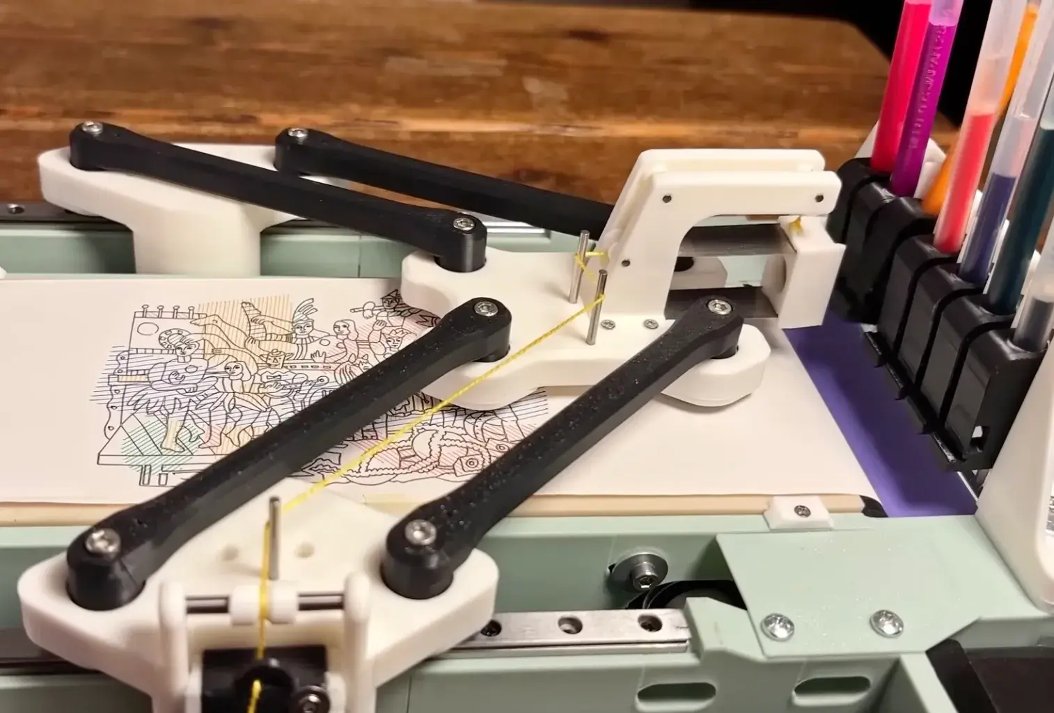
A pen plotter can be extremely simple, with two axes, a small mechanism to lift the pen, a sheet of paper and G-code, but András Vujovits deliberately complicates that recipe: two carriages drive a delta-style linkage, the paper can advance, and a changer can collect one pen before later selecting another.12
None of those elements is revolutionary on its own, yet together they change the unit of automation: the plotter receives a path along with which tool should execute it, when that tool has to change, and how the workpiece advances to the next stage.
That is why the prototype can reasonably be read as a tiny reconfigurable fabrication cell rather than simply an unusual pen printer.
Complexity moves
On a conventional Cartesian plotter, the explanation is almost comfortable: one motor moves the tool on X and another on Y. Asking for X=100, Y=50 roughly means putting each physical axis at its corresponding position.
Vujovits's machine works differently.
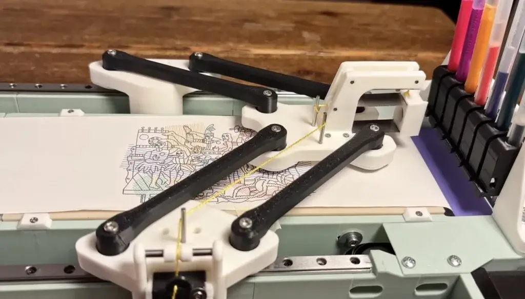
Two carriages travel along parallel rails and connect to the end effector through arm linkages, so the final pen position depends on both carriage positions rather than on independent X and Y axes.2 X and Y are coupled.
A move to the right may require both motors, and a horizontal line is not produced by one mechanical axis simply travelling horizontally, which means software has to convert the desired pen position into a compatible pair of carriage positions.
That transformation is the machine's inverse kinematics.
The payoff appears in the moving hardware, where the end effector can remain light because the large drive motors stay on the frame; Hackaday also notes the effort to keep moving mass low by moving pen-lift actuation away from the carriage instead of carrying a conventional servo on the moving head.3 Lower moving mass makes repeated accelerations easier on a plotter that changes direction constantly.
The gain is not free. The software needs an accurate model of the mechanism, the machine needs calibration, and two actuators have to cooperate to create positions that a Cartesian plotter can express much more directly.
GRBL needs a translator
The electronics are familiar: an Arduino Nano, GRBL shield and stepper drivers.2 Standard Cartesian plotter software still cannot simply send ordinary XY coordinates as if the two rails represented those axes directly.
Vujovits therefore wrote a custom preparation layer.12
The software takes an image, creates toolpaths, manages tools and produces a project plus G-code whose coordinates have already been transformed for the delta geometry.2 A normal G-code sender can then transmit the result to the controller.
That architecture keeps part of the standard toolchain alive: the motion firmware does not have to become a completely exotic control system, because machine-specific complexity moves into something close to a post-processor, a layer that knows the real geometry and translates generic manufacturing intent into movements the particular machine can execute.
Much larger machine tools use the same broad idea. CAM software describes an operation, while a post-processor adapts that operation to the axes, conventions and commands of a specific machine.
Here the idea fits around a Nano.
The changer matters more
Delta motion is the visually striking part, while the tool changer changes the type of automated job more profoundly.
The plotter can collect different pens from a rack, use them and return them.13 Hackaday describes a magnetic changer and Muji ballpoint pens in the demonstrated setup.3
A single-tool plotter needs interruption for a multicolour drawing, with somebody stopping the machine, replacing the pen and resuming; once the pens live in a rack, that intervention becomes programmable.
The production file can therefore describe both where to draw and what should draw each path.
The difference looks small because the tools are still pens. Yet it is exactly the boundary between a machine that automates motion and one that can move through several operations without an operator standing between them.
The project mentions the possibility of using other small tools,2 but the demonstrated machine is primarily a pen plotter, and a blade, probe or tool applying larger forces would change mechanics, safety and path requirements.
The changer demonstrates an architecture, not automatic compatibility with every object that happens to fit the holder.
Paper crosses the boundary
Vujovits also adds a paper-feed mechanism,2 a less spectacular component than the delta arms that changes the work cycle more than it changes the photograph.
A machine that only moves a pen over one fixed sheet still waits for a person to present the next piece of material, whereas a machine that advances its own substrate can continue into another region or prepare the next section of a job.
The small system now touches three pieces of a fabrication cell:
- position the tool;
- select the tool;
- move the work material.
This remains vastly simpler than an industrial cell containing robots, magazines, metrology and integrated safety, although the logical structure is beginning to rhyme with one because the job now combines geometry with a sequence of material states.
Why not CoreXY?
That is the obvious objection.
A Cartesian or CoreXY plotter can already be fast, precise and comparatively straightforward to control, with a more conventional software ecosystem, geometry that is usually easier to reason about and no fundamental obstacle to adding a tool changer. The prototype therefore demonstrates a design trade rather than universal superiority for delta kinematics.
The main motors remain on the rails and the end effector can stay light, but software then needs to know the geometry and calibration becomes more directly tied to the mathematical model of the mechanism.
For a one-off machine, that complexity may be perfectly reasonable, especially when exploring the kinematics is part of the project itself.
For a product manufactured by the thousand, the arithmetic changes. A few extra parts, ten minutes of calibration or custom software acquire a very different cost after multiplication by a production run.
The prototype is therefore more useful as an architectural demonstration than as a verdict on the best possible plotter.
Programmable change
Digital fabrication is usually described by machine category, such as 3D printer, laser, CNC or plotter, while in a real workshop a surprising amount of time disappears between operations as somebody changes a tool, flips a part, loads the next sheet, opens the correct file or checks that the physical setup still matches the program.
Vujovits's plotter already automates several of those transitions, which is why the pen changer and paper feed are more interesting than the theatrical movement of the arms alone: they move automation from motion inside one operation towards the passage between several operations.
At small scale, that is exactly what a fabrication cell tries to do.
The next useful step may have little to do with speed and much more to do with making the machine aware of which tool it carries, which material is in front of it, what has just finished and what has to be prepared next.
At that point the plotter gradually stops being only a machine that draws and starts becoming a system that organises work.